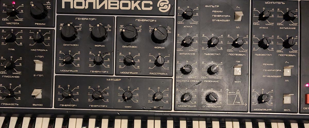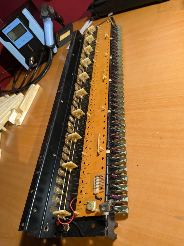


Yesterday, I noticed that one of the two oscillators stopped working again. I decided to open up the Polivoks once more to figure out where the issue was coming from this time. I also thought that now that I had the Polivoks open, I might as well check out a few mods.
1. Another defective oscillator
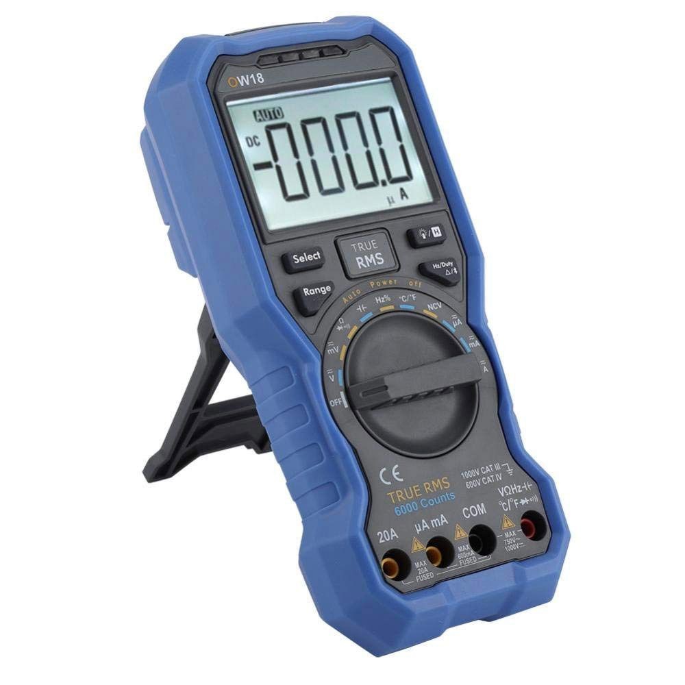
The last time I worked on the Polivoks, I had just built an audio probe. It worked fairly well, but I wanted to go a step further, so in the meantime, I bought an oscilloscope. I ended up getting the Rigol DHO804, a 4-channel scope that should be more than enough for this kind of work. I immediately put it to use to look for a waveform on the oscillator boards.
As soon as I started measuring, it became clear that there was no signal on one of the boards. Fortunately, it wasn’t the board I had worked on before. Could it be the same issue?
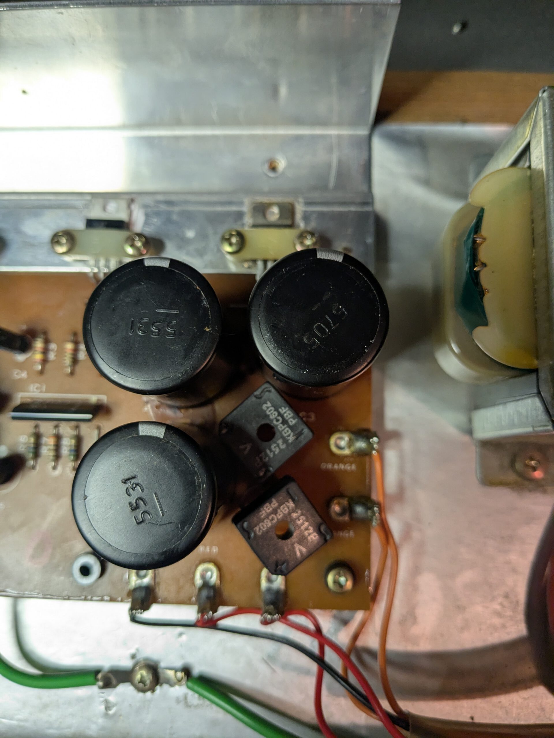
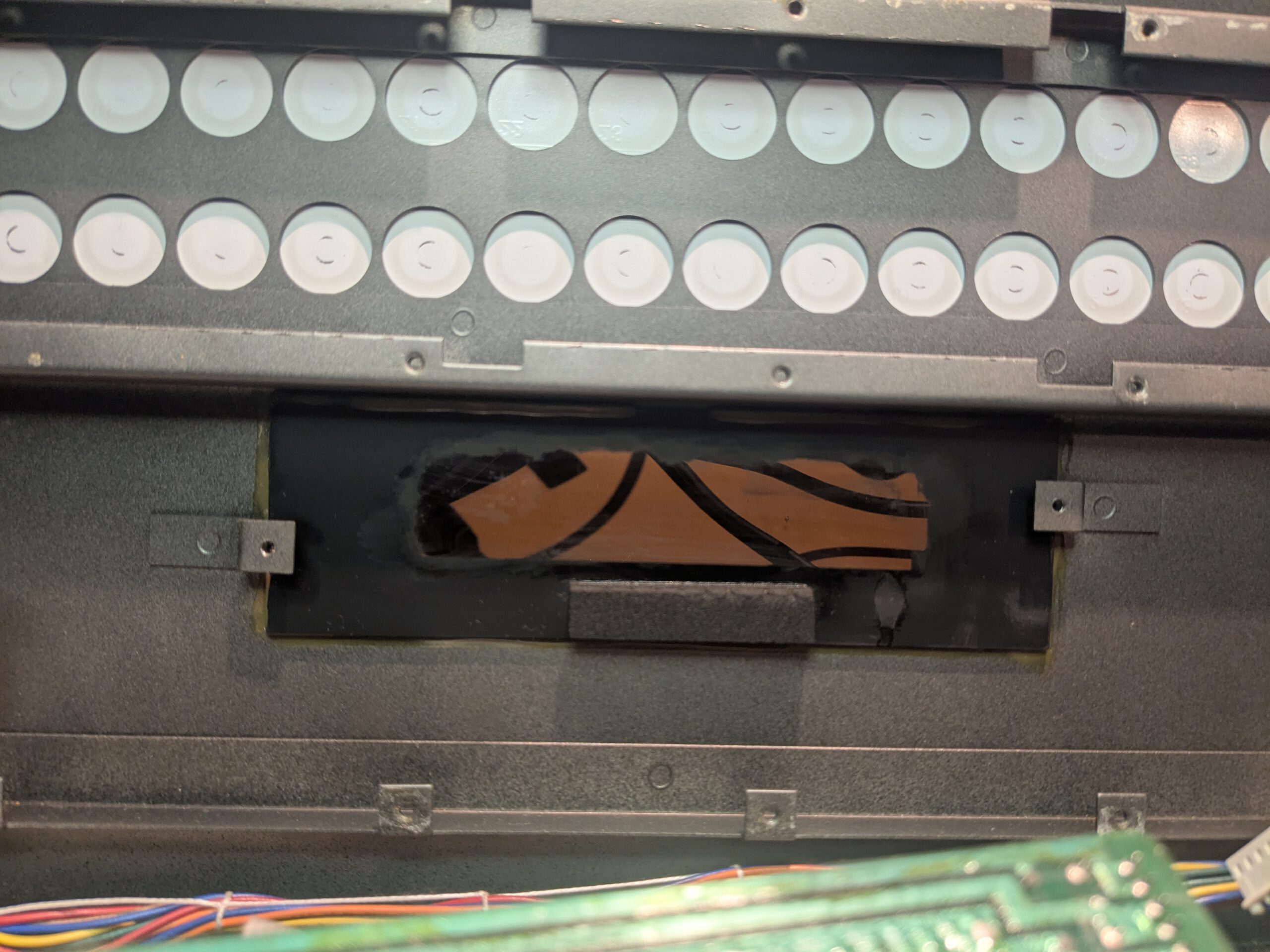
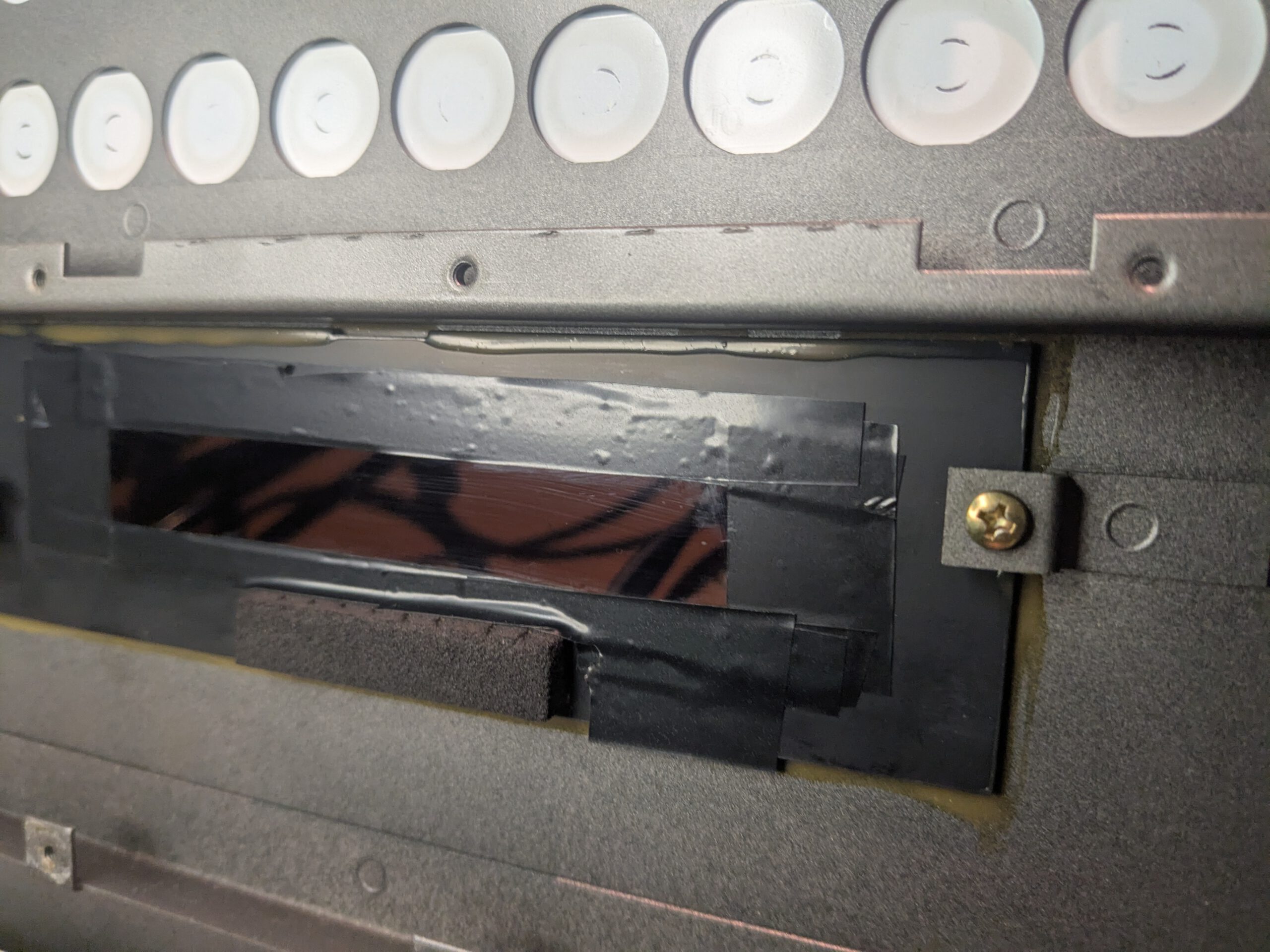
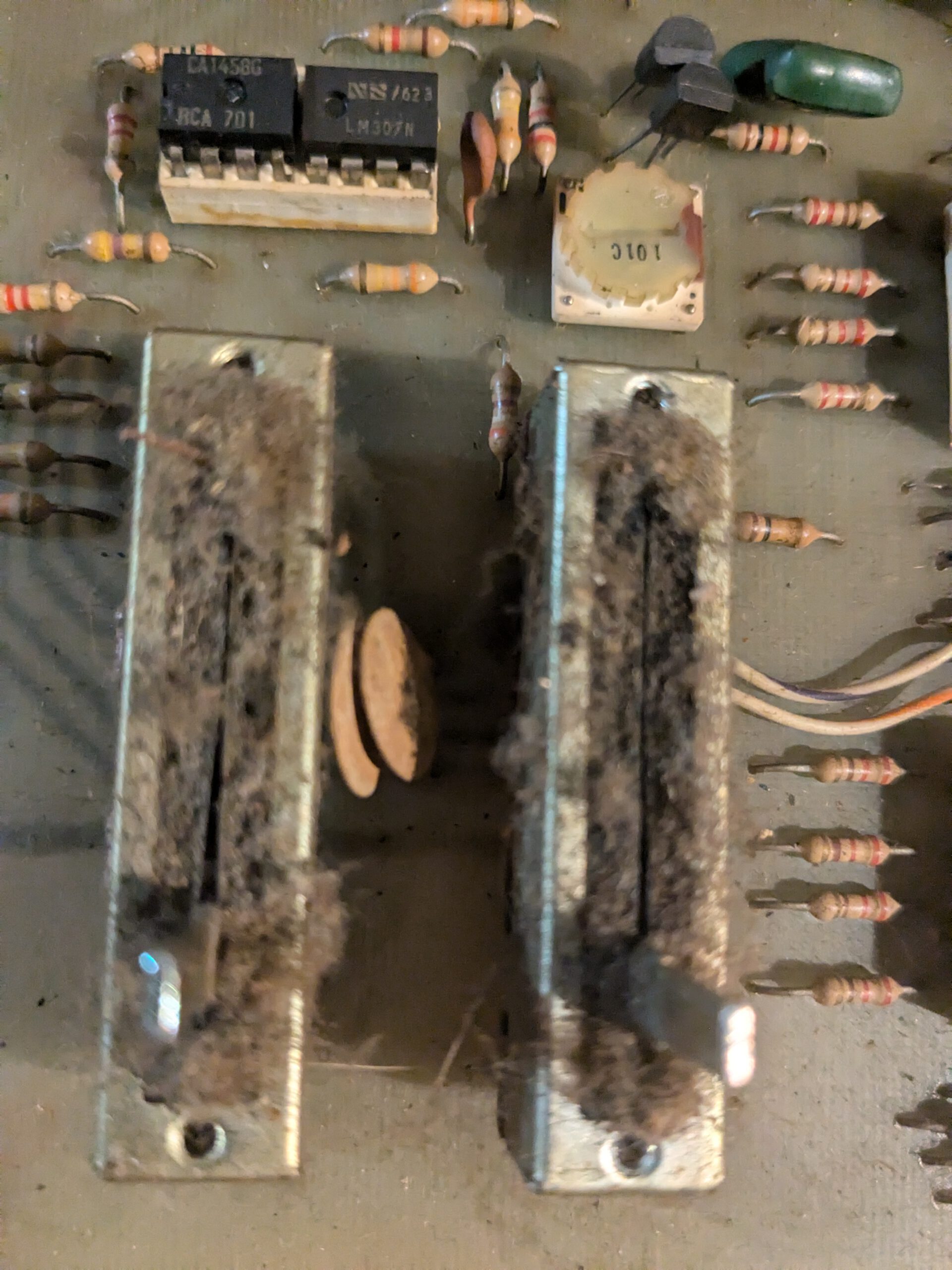
In any case, there was no waveform on pin 6 of IC A7. That meant something went wrong before that point. I measured the transistors, and they were all still fine, as were the resistors and capacitors in that direct area. Luckily, I had the second board that was working properly, so I could use it for comparison. After some measurements, it became clear that there were several points showing much higher voltages (12V). See below. I decided to measure the resistors, and I noticed that R23 had a much higher resistance than specified. It measured 2.9kΩ instead of 100Ω. I then swapped the 100Ω resistor from the good board to see if the waveform would return, but unfortunately, that didn’t fix it. The voltages were still high in some places, although pin 5 of A5 now showed much better values! I then measured some values on A4, and on one pin, I measured 12V, whereas on the good PCB, that wasn’t the case. Internally, the IC likely shorted, causing a higher current through resistor R23. It then overheated and likely caused the resistance to permanently increase. Fortunately, I had bought a spare KR198NT1A from Erica Synths, which I could now use.
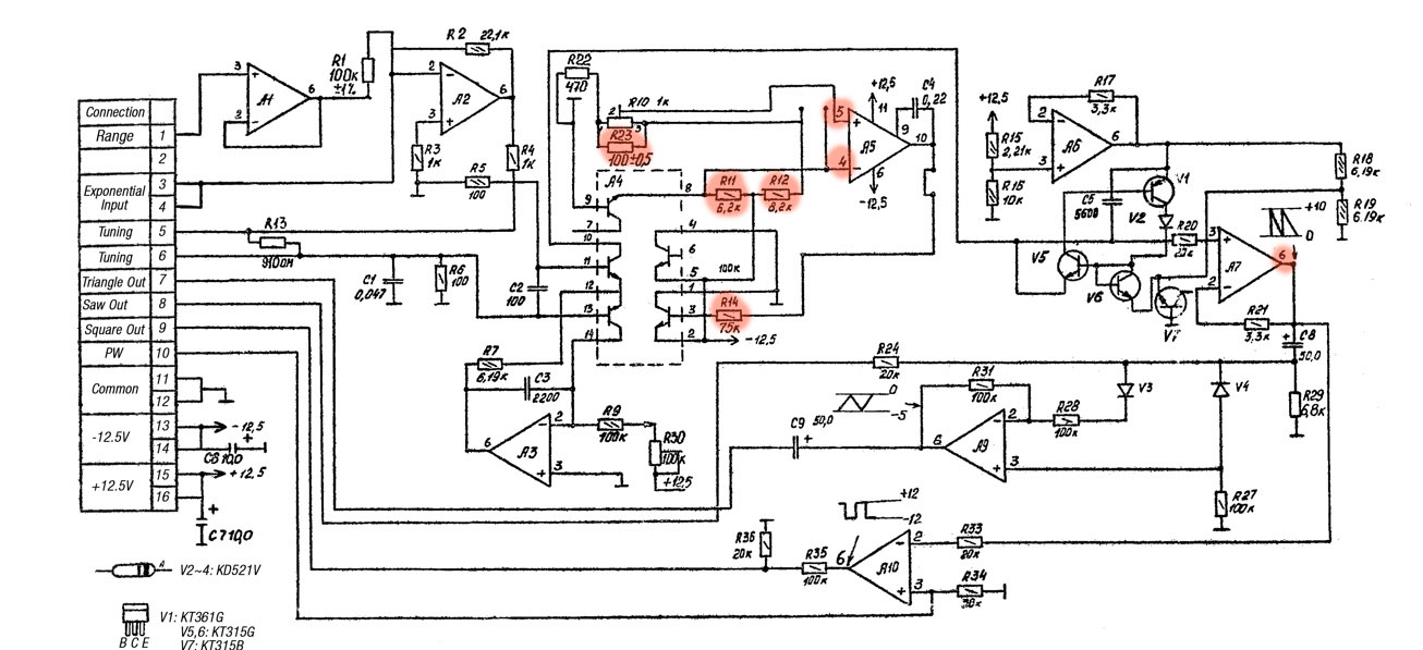
After soldering, I measured again, and yes, the waveform was back! The only thing that stood out was that the PCB was drawing more current than the good board. It was now drawing 0.035A instead of 0.015A. Even though the oscillator seemed to be back to normal, something still wasn’t quite right. I decided to measure and compare a bit more around the components I had replaced. It quickly became apparent that pin 10 of IC A5 had too low of a voltage. I tested the capacitor C4, which sits between pins 9 and 10, and it was fine. I then swapped IC A5, and that turned out to be the issue. This is a dual opamp, and likely, one of them had failed, causing pin 10 to show the wrong value. When I powered the PCB with the new IC, the current draw returned to 0.015A. So, I unfortunately need a new IC. It’s the KM551UD1B, which is quite rare, and there isn’t even a datasheet available for it. Eventually, I managed to buy a couple from a Latvian store (http://evita.lt) for 2 euros each.
So, the cause was a damaged resistor and two faulty ICs. One was probably the cause of the other. Fortunately, I still had one spare left. We have a working Polivoks again!
2. Cross modulation mod
I noticed that my cross modulation wasn’t working properly. This gave me the opportunity to try a simple mod I’d seen that increases the range of the cross modulation. Additionally, I had a few pots that I’d like to check if it’s possible to clean them. To get to the pots, I needed to free up the mainboard.
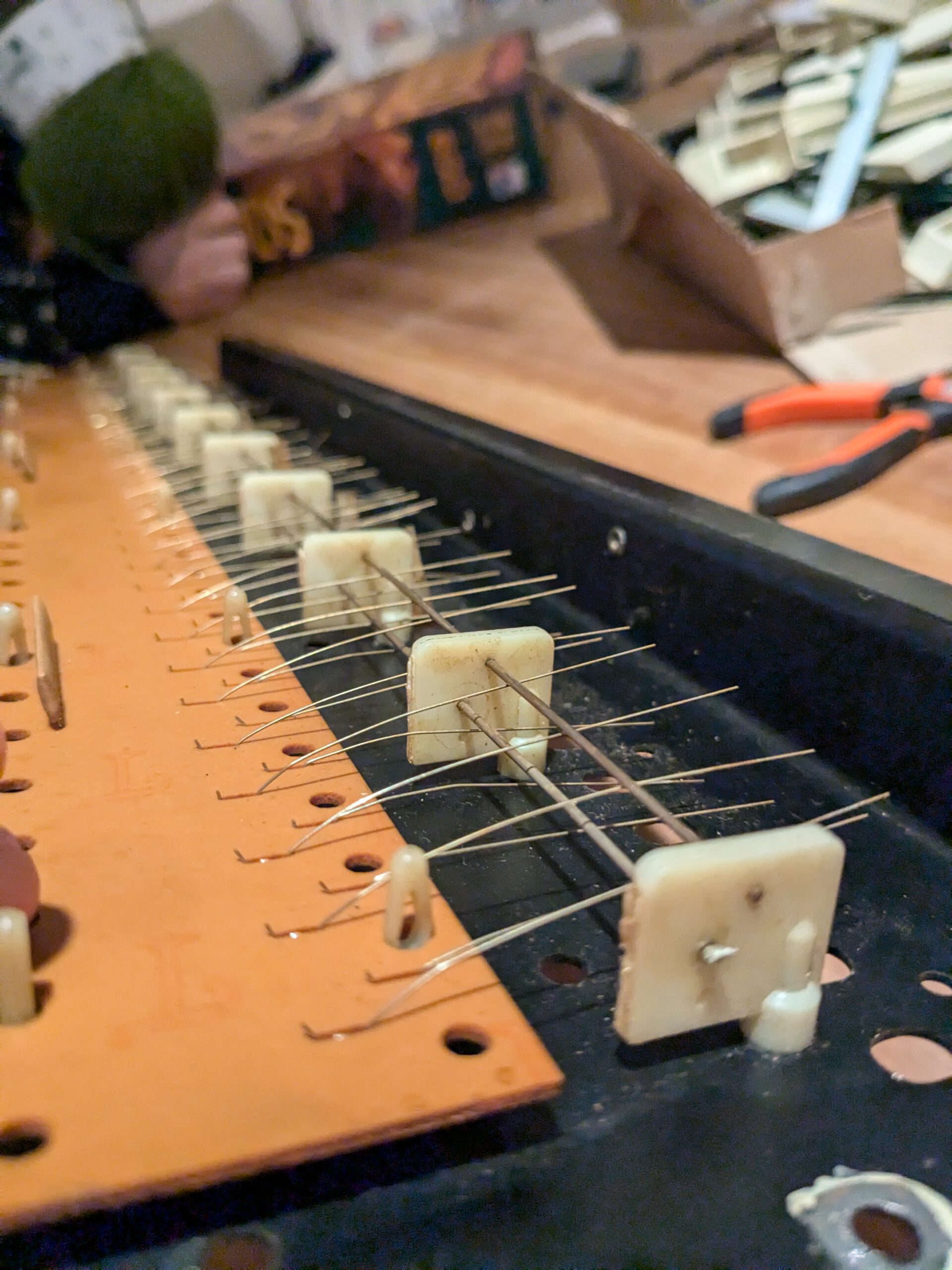
This starts with removing the knobs ont he front panel. A few tips to do this proper:
1. The knobs come off easily by pulling, but be careful with the large ones. You don’t want to lose the steel shims inside the knobs. I once removed the knobs, and the shim fell right trough the Polivoks. Aside from the fact that this can cause a short circuit, it was also a real hassle getting them out again. My tip: Hold the Polivoks upside down and remove the large black knobs then. The small knobs don’t have these shims.
2. After removing the knobs, lay them apart exactly as you removed them. Inside, the knobs are positioned differently, so it might be that a knob no longer fits on another potentiometer.
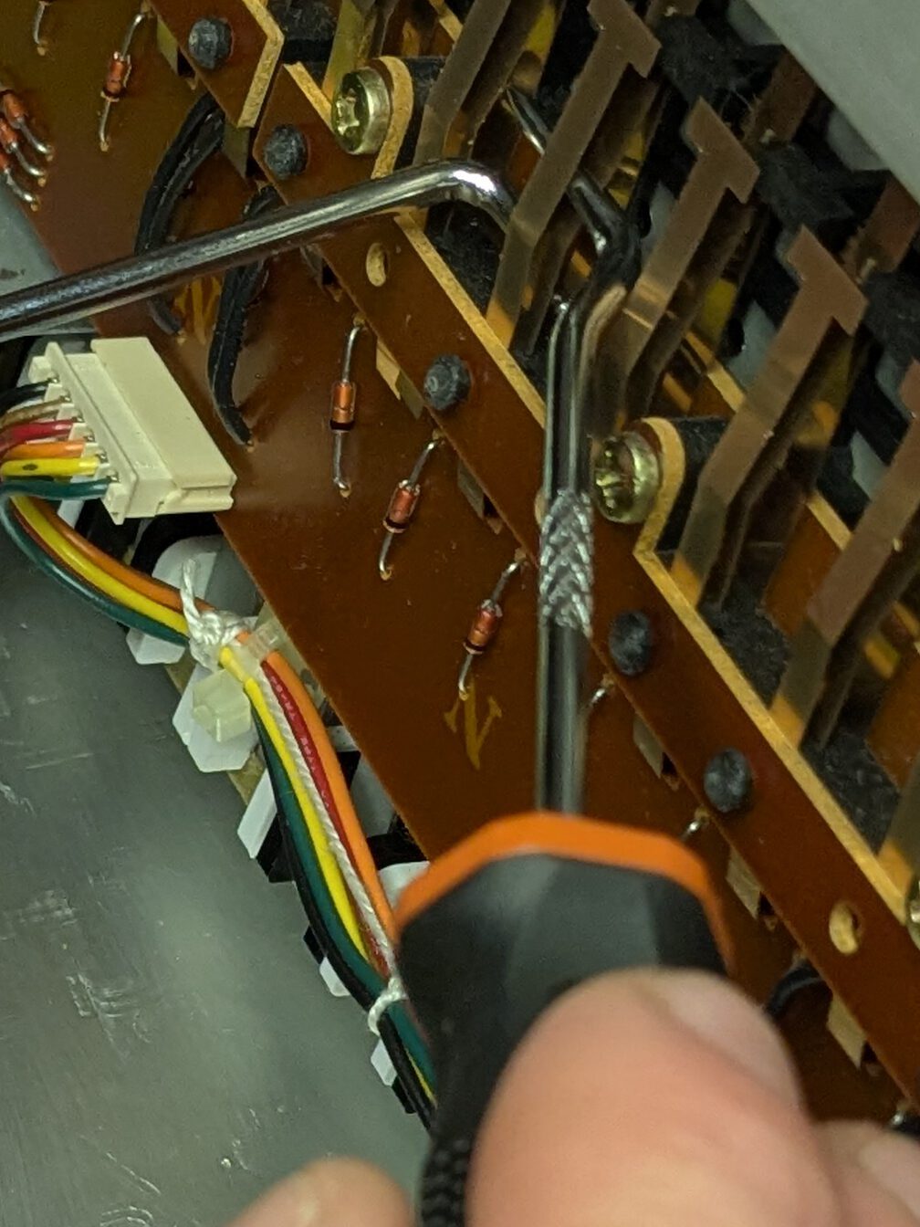
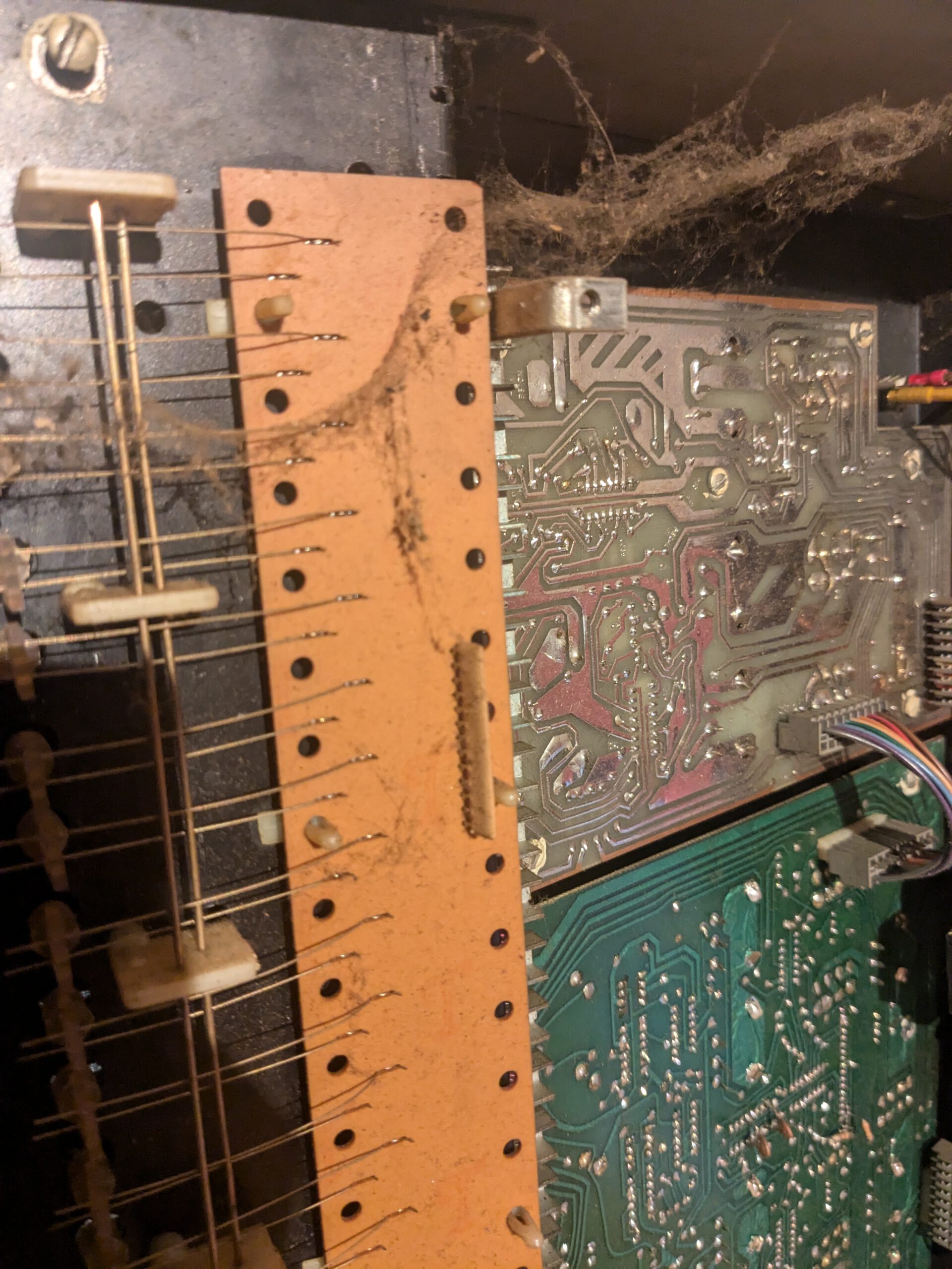
The mainboard of the Polivoks is not easily accessible. First, you need to remove the cards from the slots, disconnect two connectors, and desolder six white wires. Be sure to mark them before you remove them. This will save you a headache later when you can’t remember how to solder them back.
The mod involved replacing resistor R64 with a wire. This was simple to do. The preparatory work was trickier. I was really curious if this would have an effect, so I put everything back together afterward. The result was noticeable. There was now a much clearer effect.
3. Filter mod and potmeter cleaning
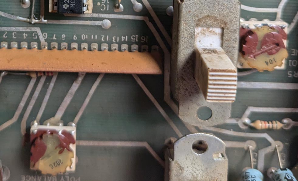
Another mod I wanted to do was to increase the range of the filter. After position 3, the filter pot didn’t do much anymore. It seemed like it would be better if the range was spread out more. The filter was on the other mainboard, which was a little trickier to get to than the other one. Only one ground wire needed to be desoldered, but the fuse was in the way. After some adjusting, I was able to tilt the board so that the transformer wires didn’t need to be desoldered.
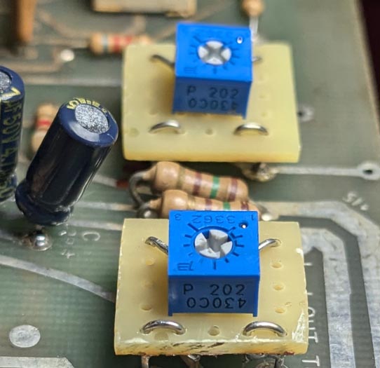
This mod wasn’t harder than the other one. Resistor R87 had to be replaced with a 120k resistor. I didn’t have a 120k resistor, so I soldered a 100k and a 22k in series.
Since I had everything open, I also decided to clean the filter pot. When it was fully closed, I heard an unfiltered distorted signal. I was thinking about replacing the pot, but I wondered if it was possible to clean these pots internally. If it didn’t work, I could always buy a new one.
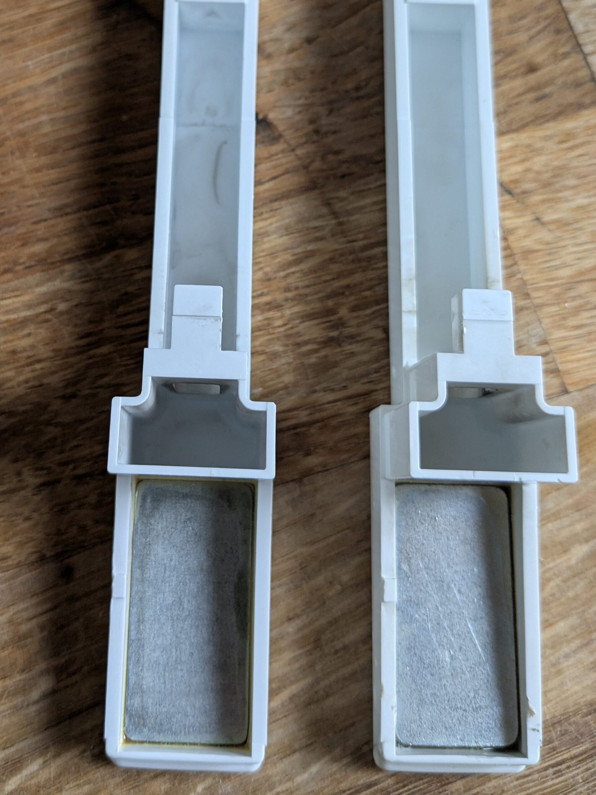
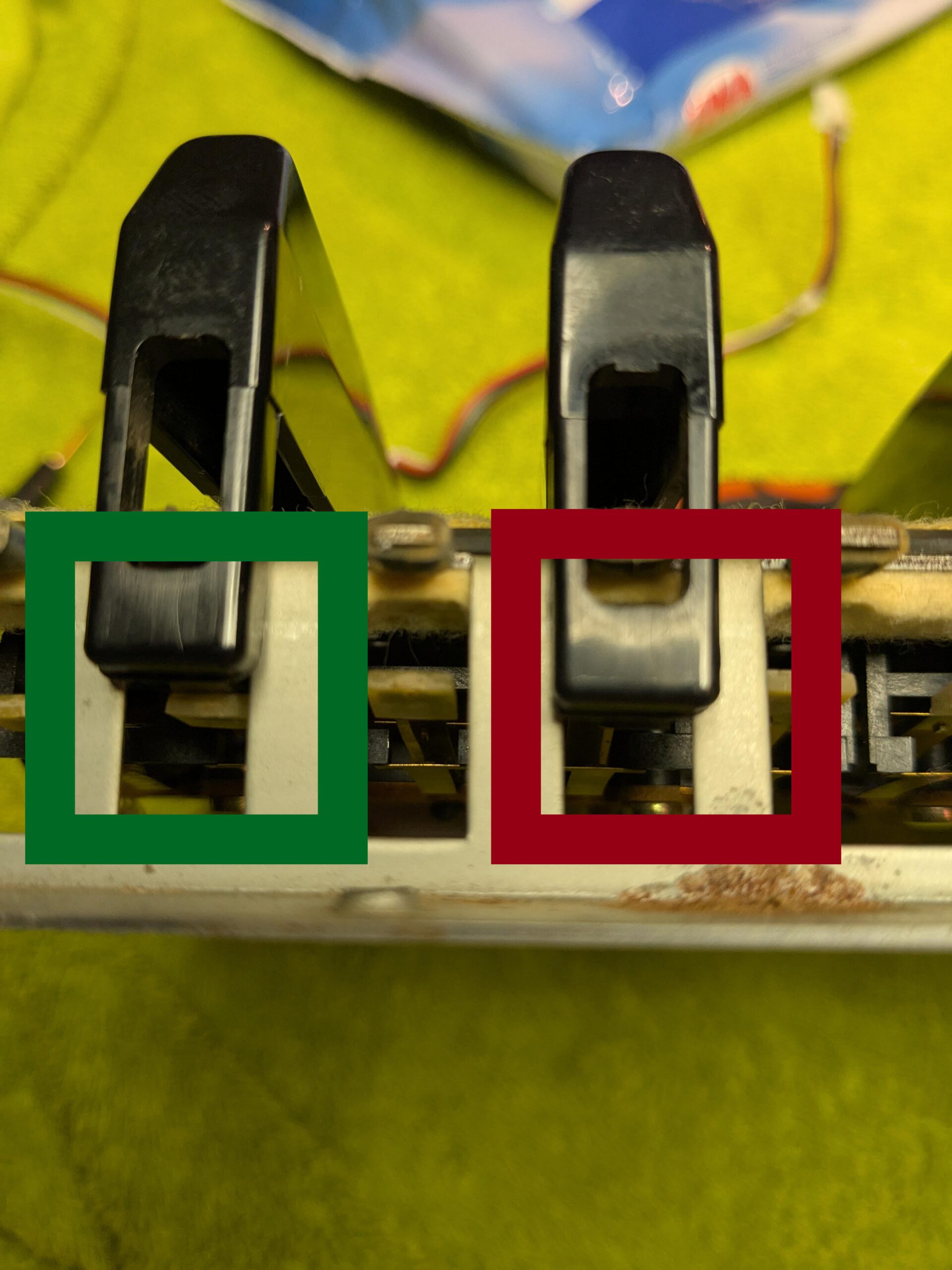
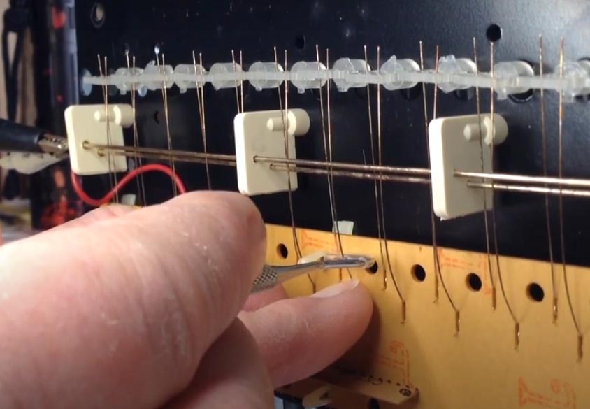
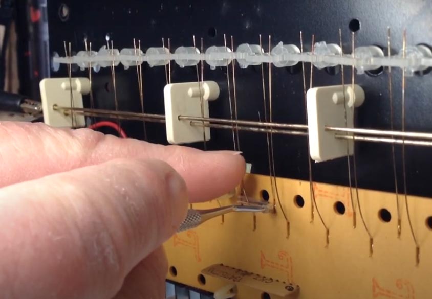
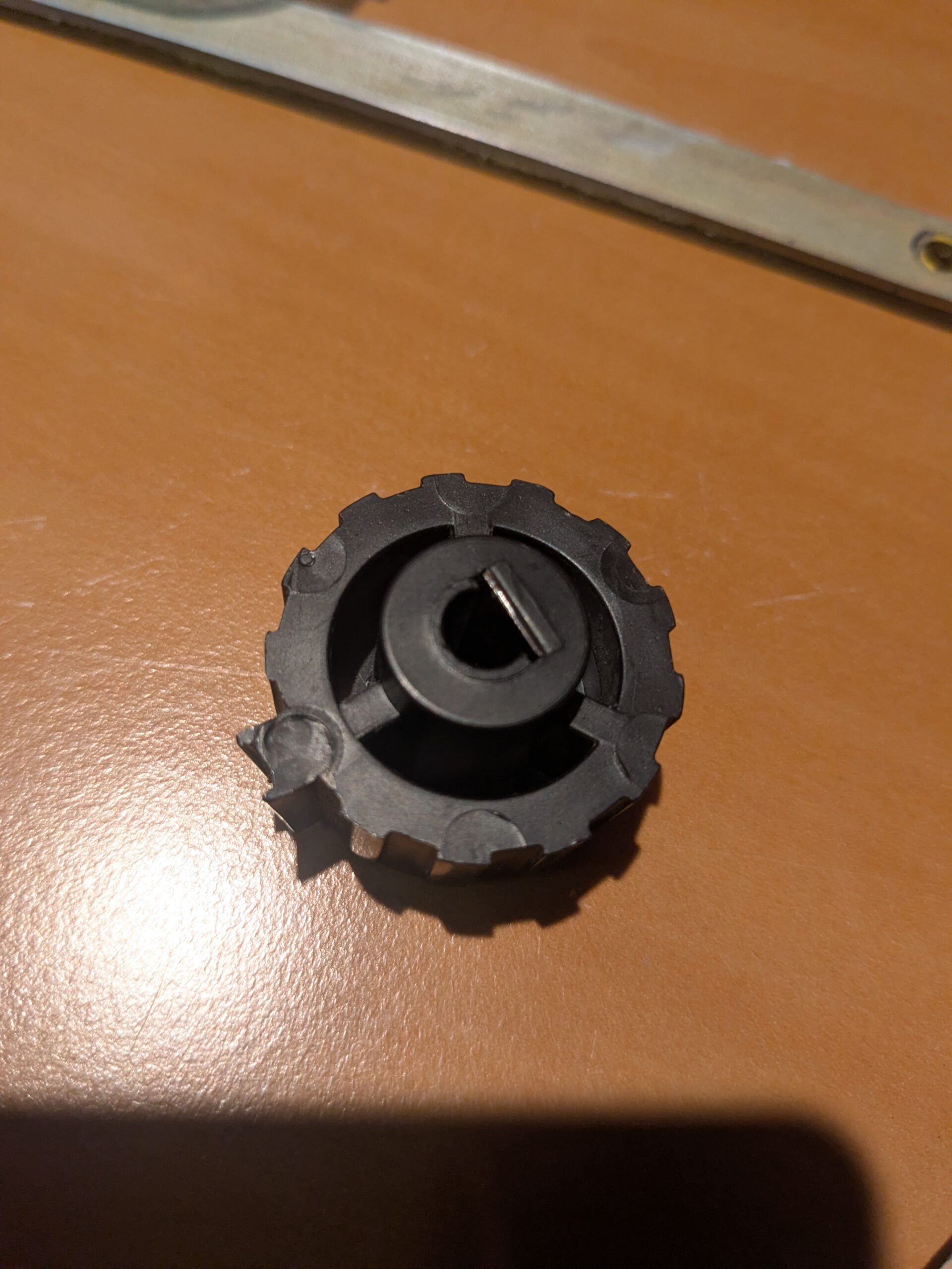
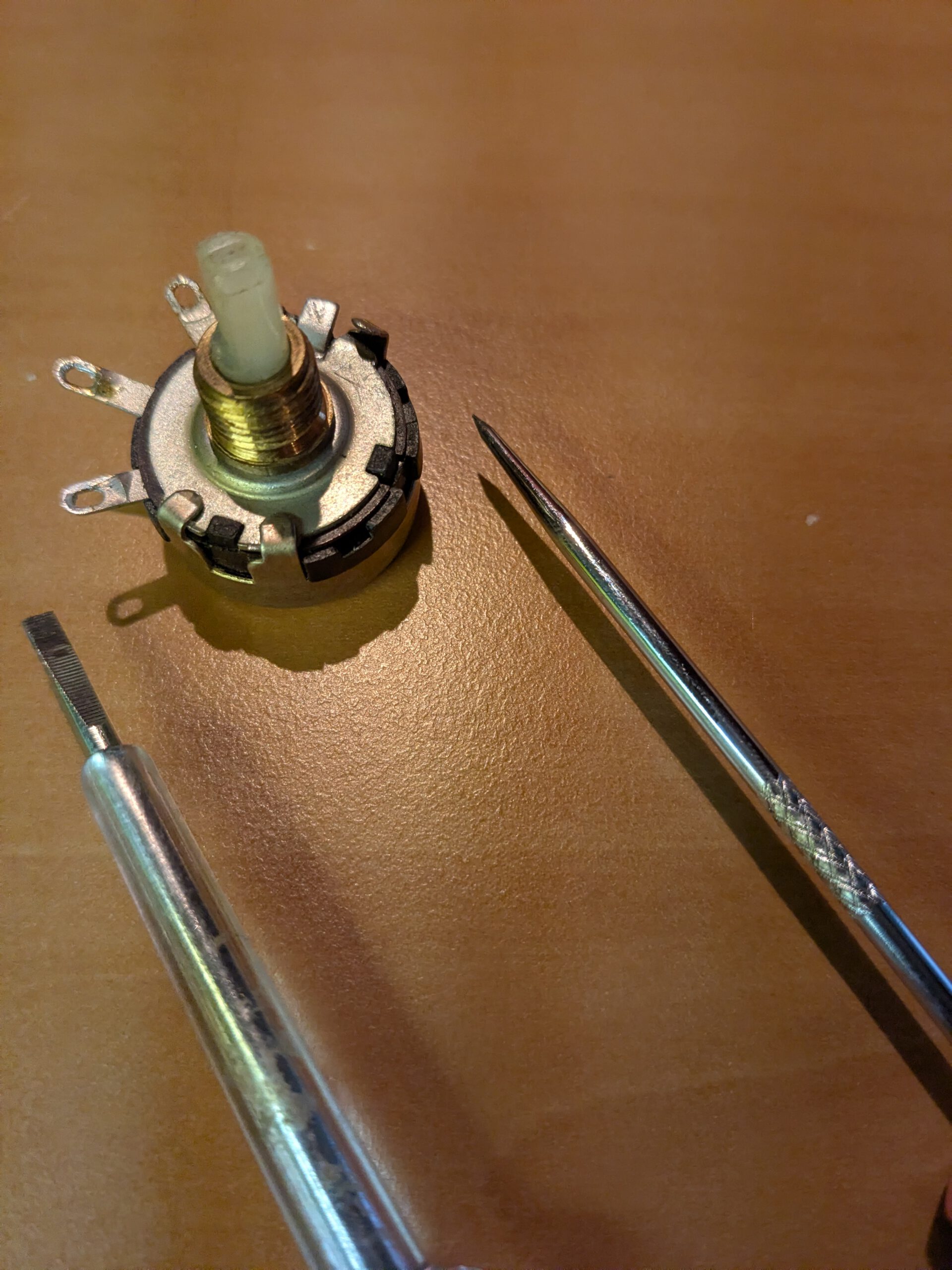
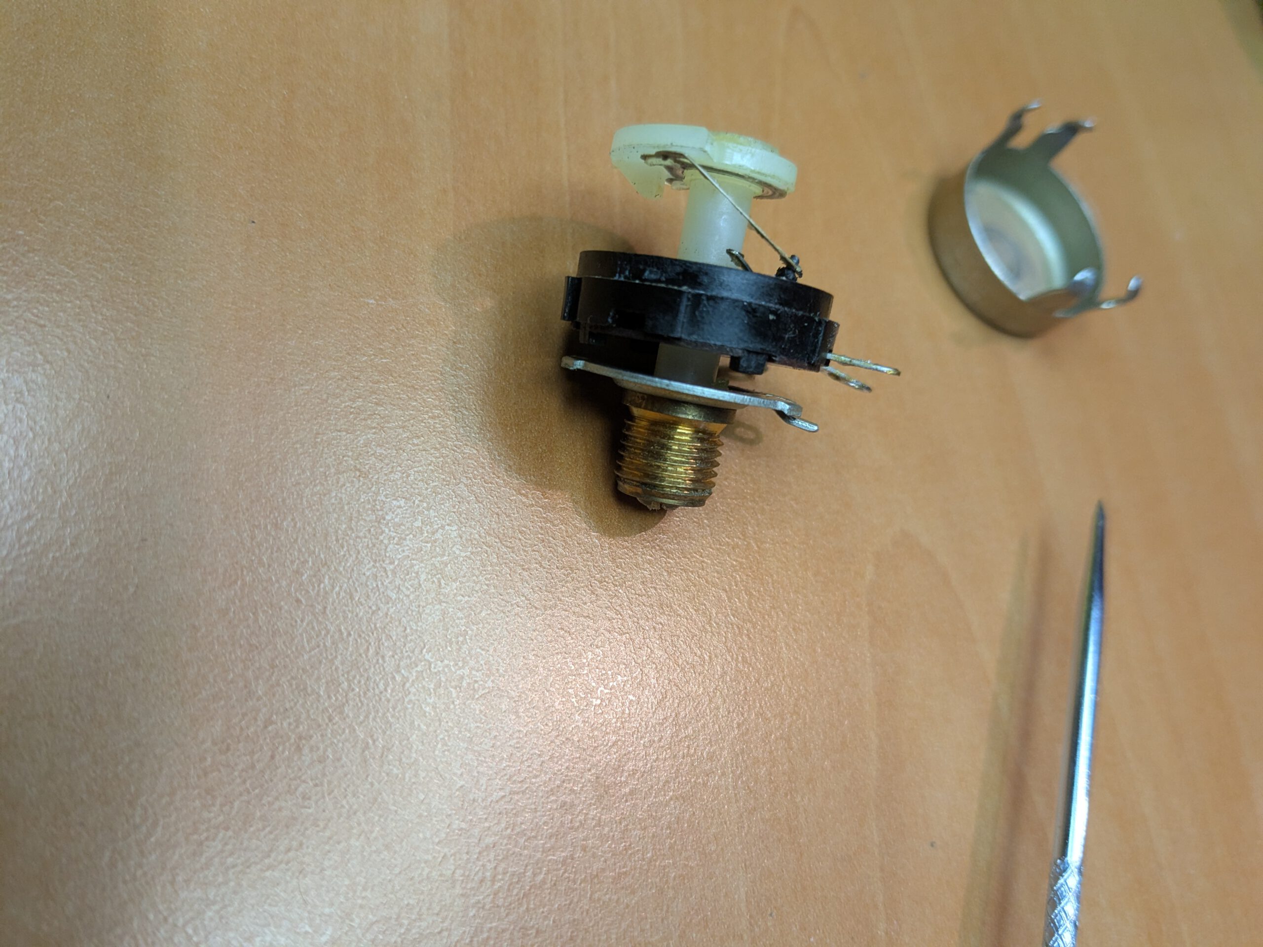
Once desoldered, I used a pointy tweezer and a small flathead screwdriver. There were four clips that could be loosened with the tweezer. With the screwdriver, I was able to easily bend them upwards (see photo 1). In photo 2, you can see the wiper at the top which moves over the carbon track (see photo 3). If you look closely in photo 2, you can see a tiny element that glides over the carbon track. It’s loose, so be careful not to lose it. I cleaned the wiper and the carbon track with DeoxIT F5 and a cotton swab. After that, I reassembled it without the metal cover. I first wanted to check if everything was making proper contact and that the resistance gave the correct values. Luckily, everything was fine, so I put the cover back and bend the clips back. After that I soldered it back onto the mainboard.

I was curious if the range had improved and (what I found even more important) that the pot now no longer produced any unwanted noises. I put everything back together and… it worked perfectly! The noise on the lowest setting was gone, and the range was extended from 1 to 3, all the way to 1 to 5. This also gives me the confidence to clean more pots. There were still a few that were dirty.
4. Conclusion
It feels good to have tackled some new issues again. I’ve learned how to clean potentiometers, and it gives me confidence knowing that if something goes wrong with them in the future, I can fix it myself. I’ve seen a few stories online claiming that if you have trouble with these pots, you’re out of luck, but that seems pretty exaggerated. Sure, if you had to clean every single one by hand, the costs could add up, but if you’re careful, it’s absolutely doable. The mods turned out well, and the oscillator is working again, so overall, I’d call this another success!