
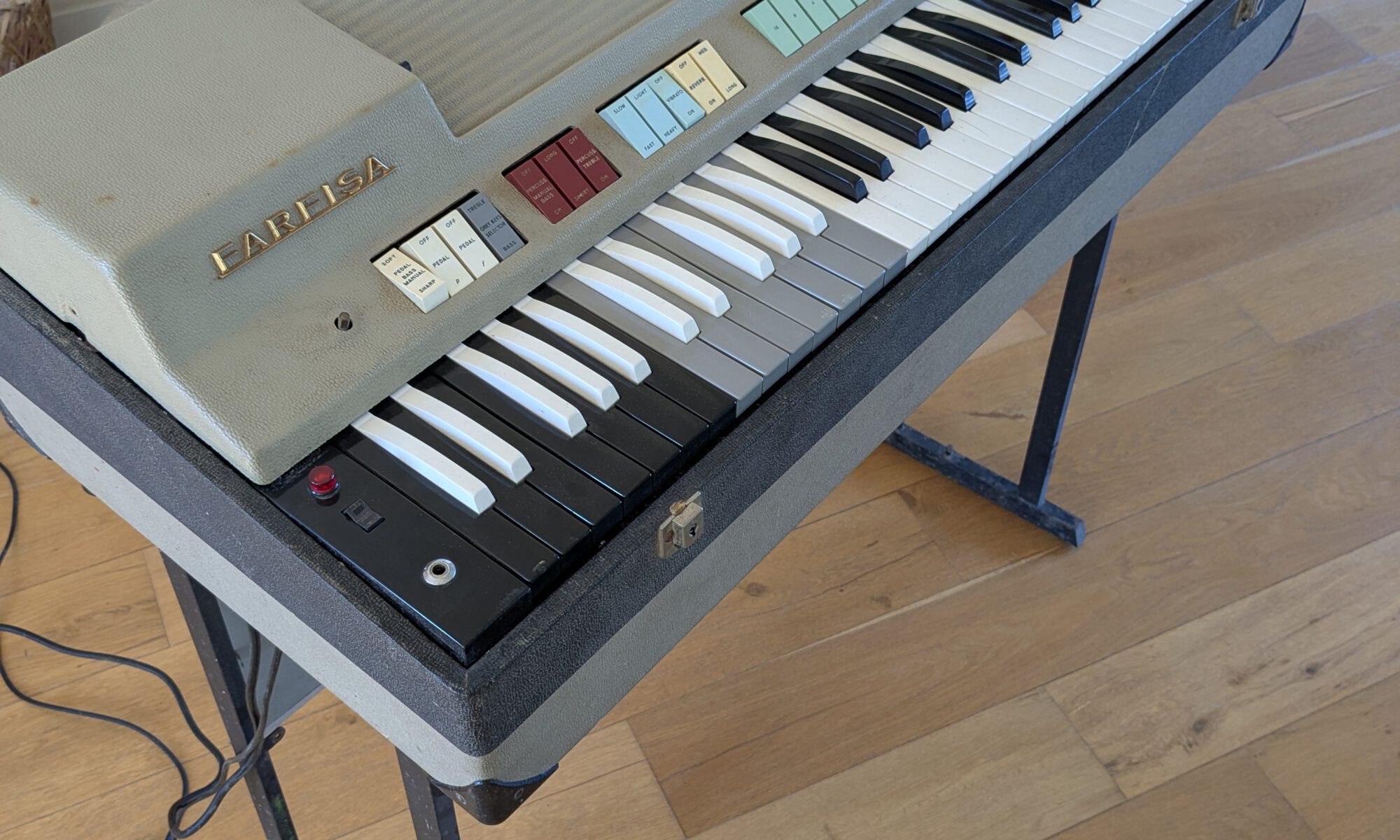
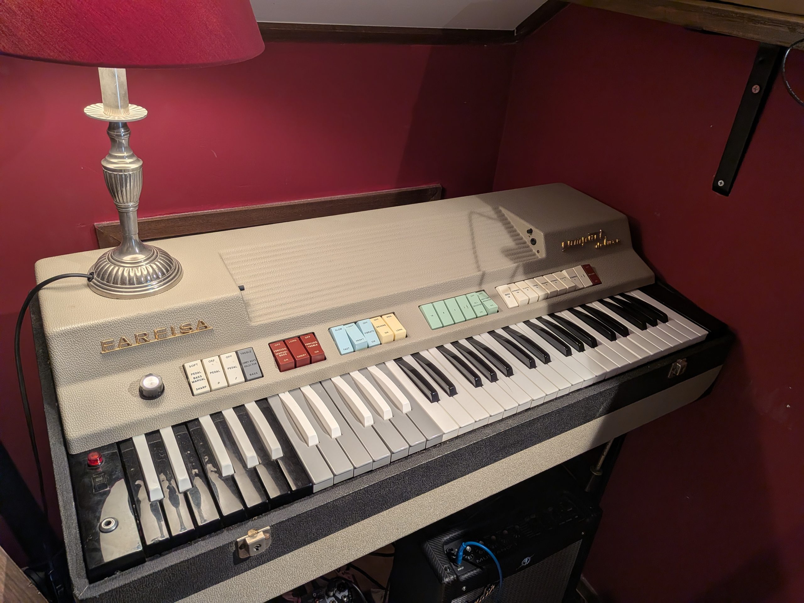
This time an organ for the workshop / studio: the Farfisa Compact Deluxe.
I collected records for a while, and my interest has always been in early 70’s library and soundtrack music from France and Italy. Those records often had a certain sound that I loved and that I sometimes wanted for my own productions.
The Farfisa Compact Deluxe is an organ built in the 60s and widely used at the time. It has a very distinct character and, alongside the Hammond, has become a classic.
Unfortunately they don’t often show up on auction sites nearby, so I thought it would be fun to have one shipped from Italy.
I saw one listed as “for parts” on Italian eBay with €40 shipping. The price was fine too (400 euro) , so I decided to take a gamble. It actually looked good for its age, and it came in its own case, which was convenient for shipping.
The Farfisa arrived well packed and undamaged. Once set up, it was time for a first inspection.
There must be a thing or two wrong with it.
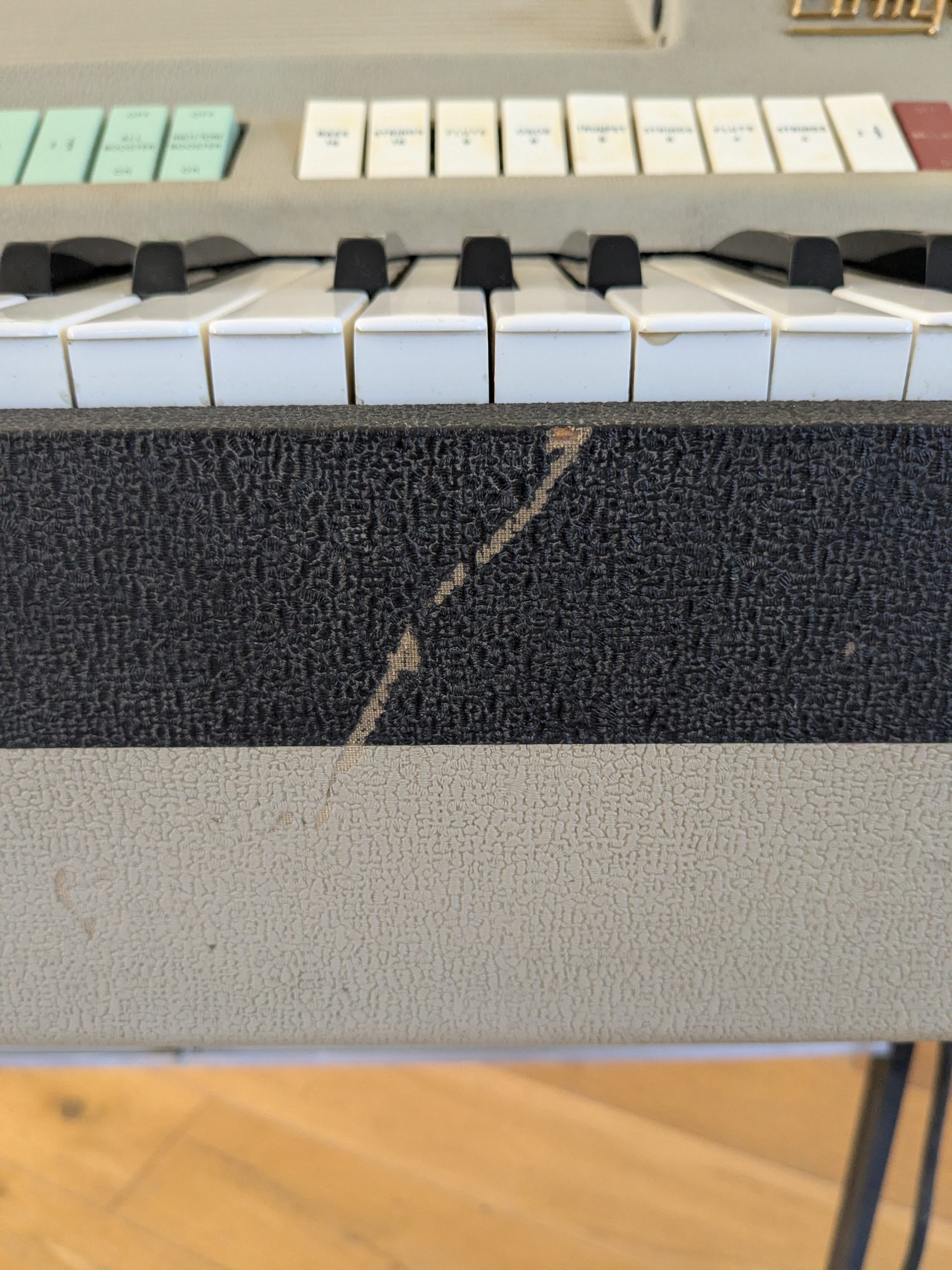
- There was a scratch on the black tolex. I touched it up with a black pencil.
- A capacitor was missing on the right-hand side. It had apparently fallen off, because I found it later in the case.
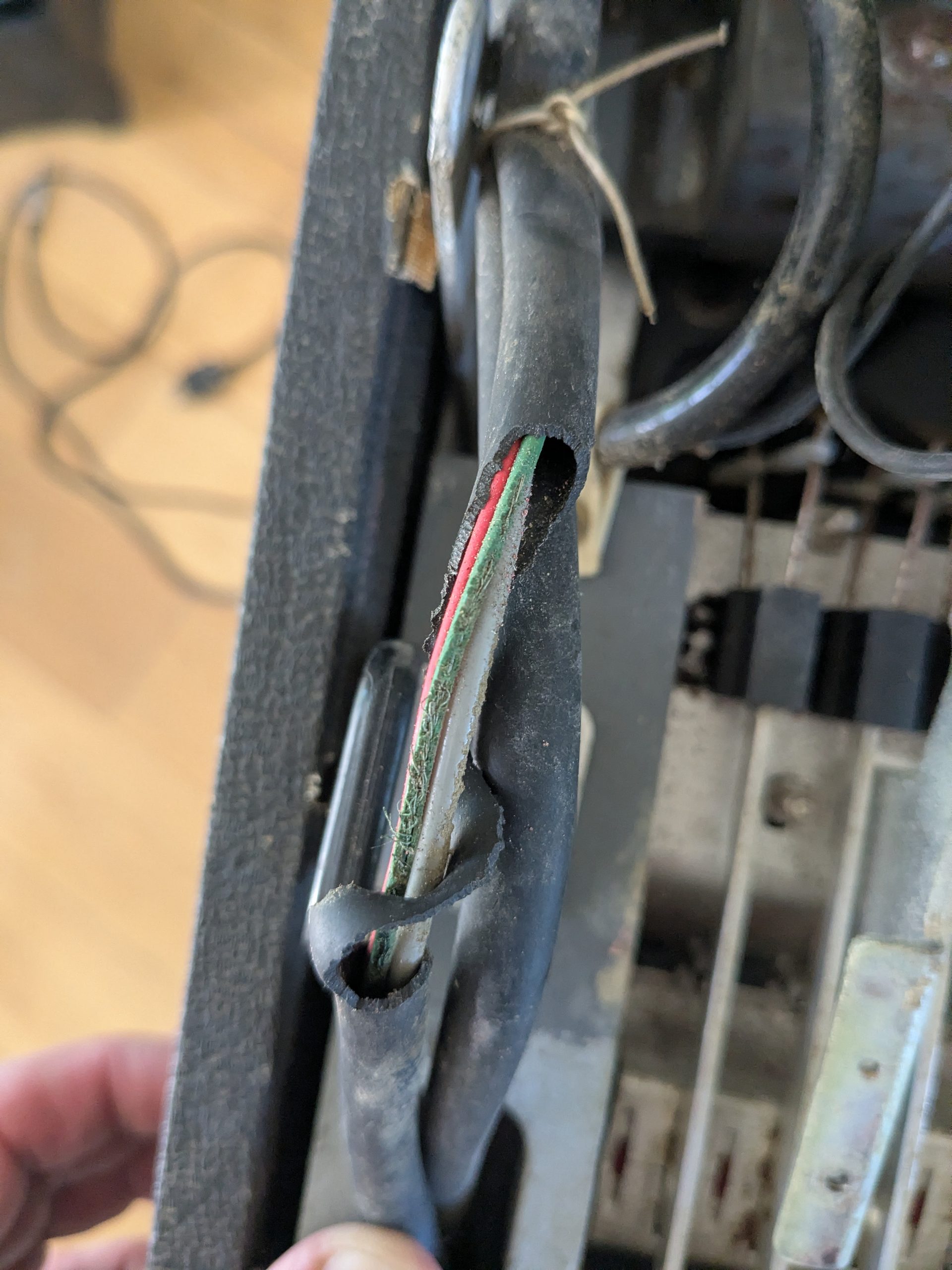
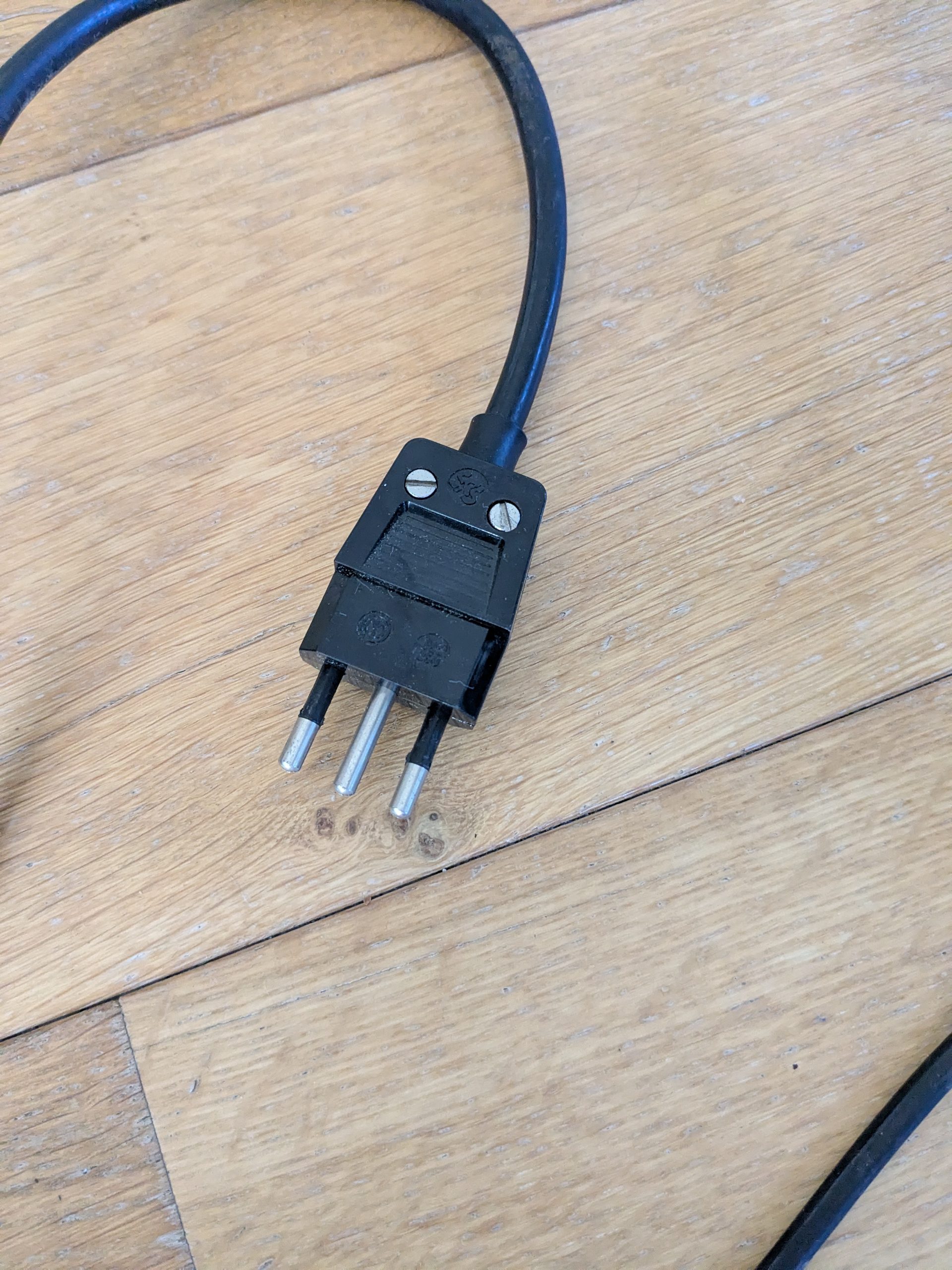
- The power cable was worn and danmaged. I also have to replace the plug. It doenst fit my socket with the long earth pin.
- The voltage selector was missing its cap with the selector and the fuse…
- An oscillator board (F) is missing.
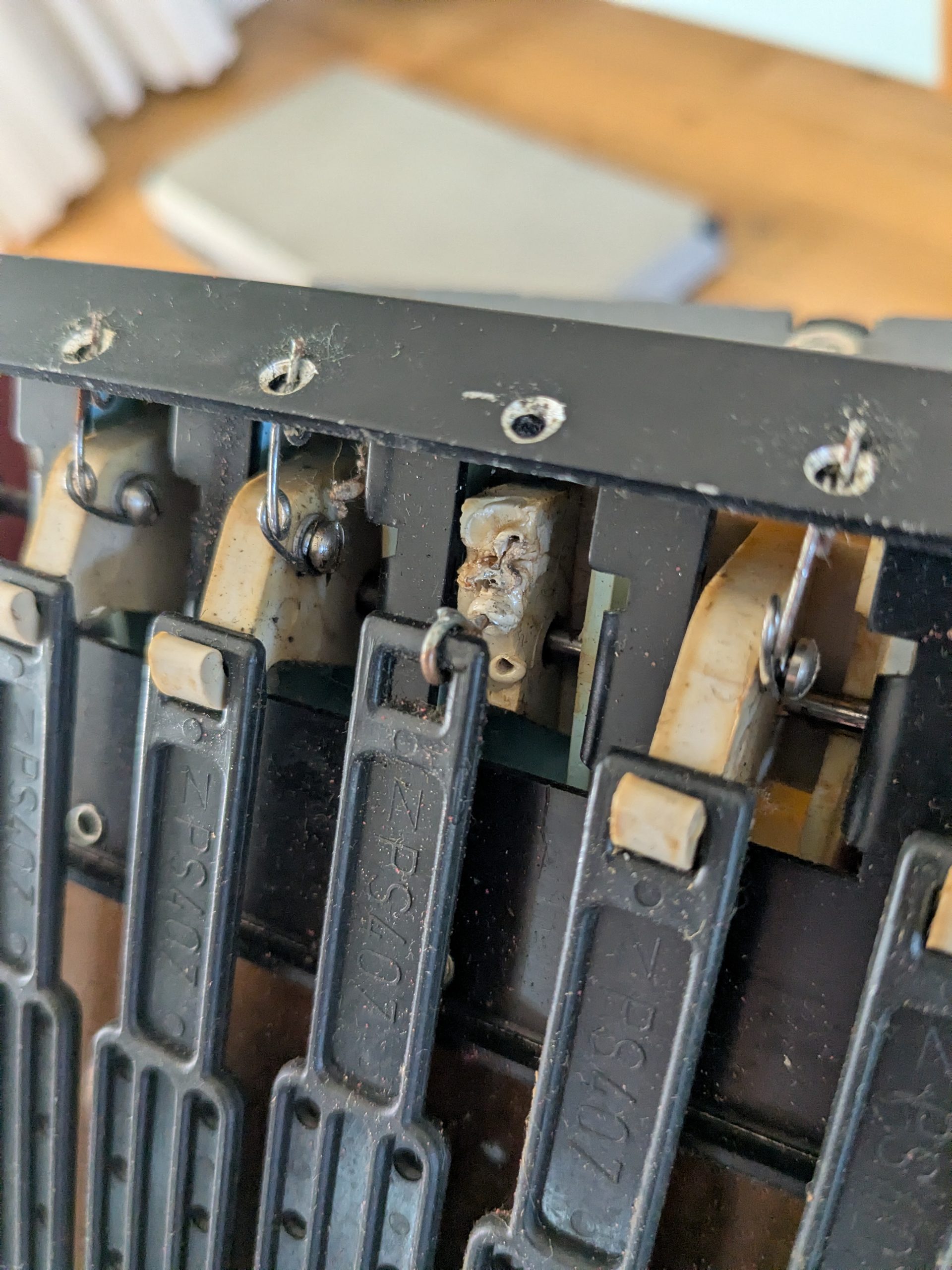
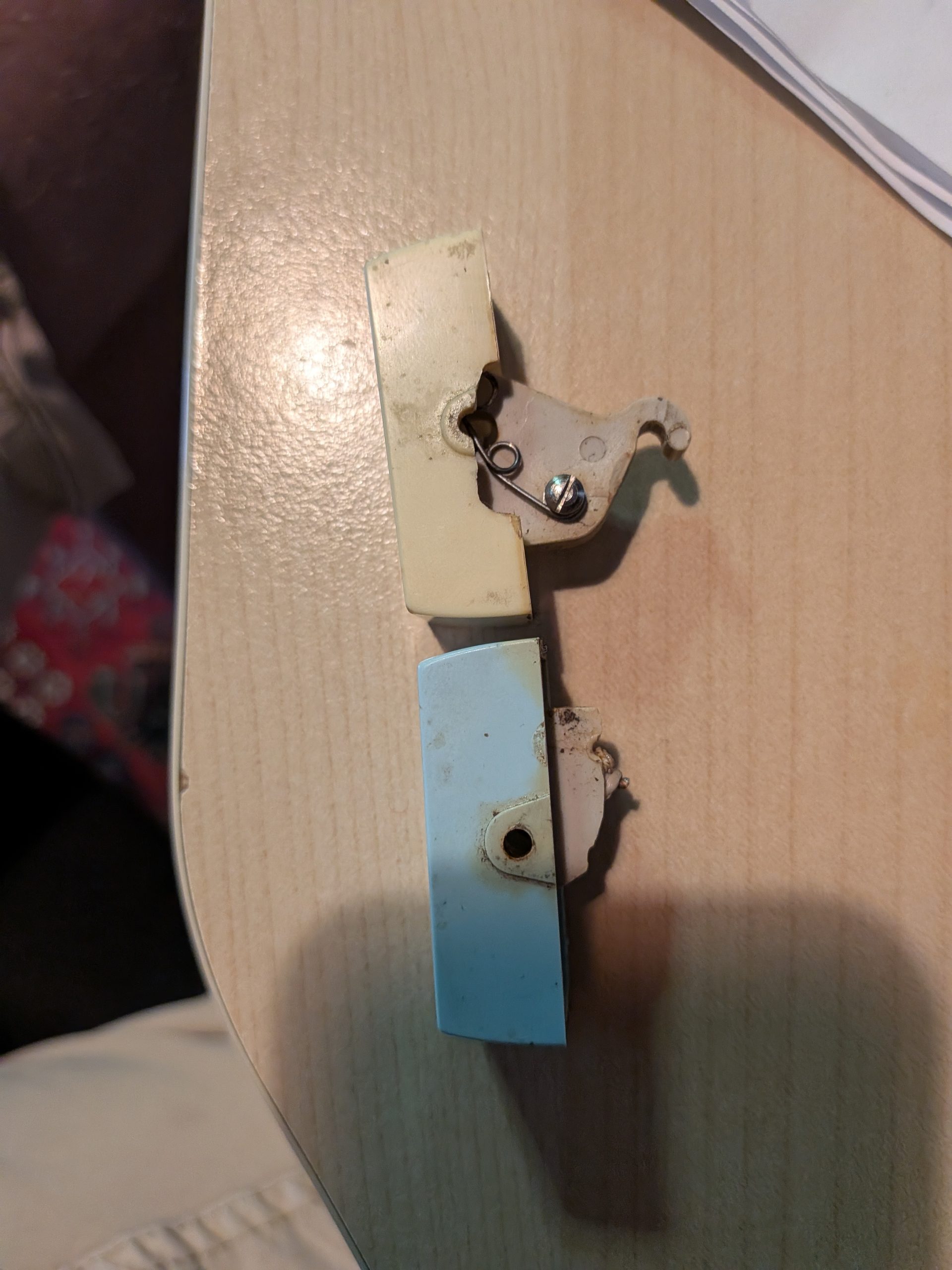
- Two switches were broken: the vibrato and one of the voice tabs. I was able to fix the tab quickly since the broken piece was in the case. I glued it back with superglue. The vibrato is in worse shape and needs to be replaced.
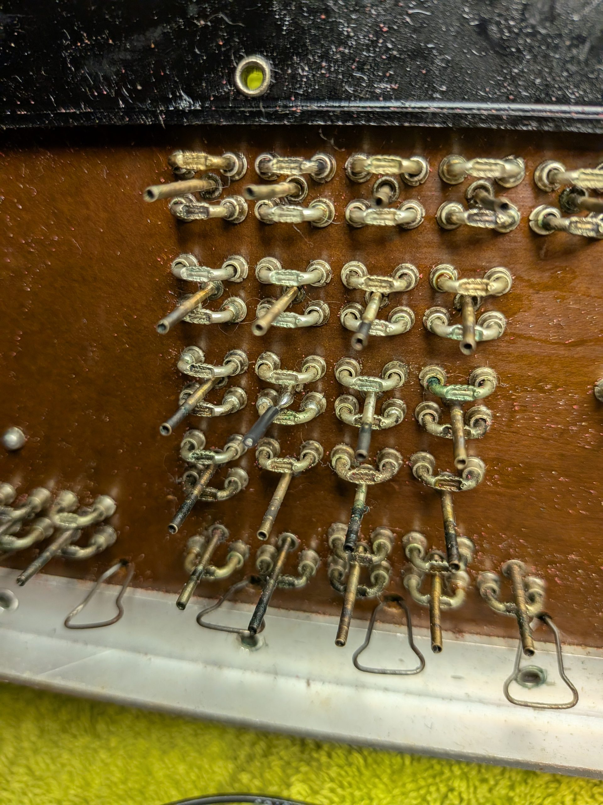
- All the spring contacts under the switches are dirty and some are corroded. That means cleaning.
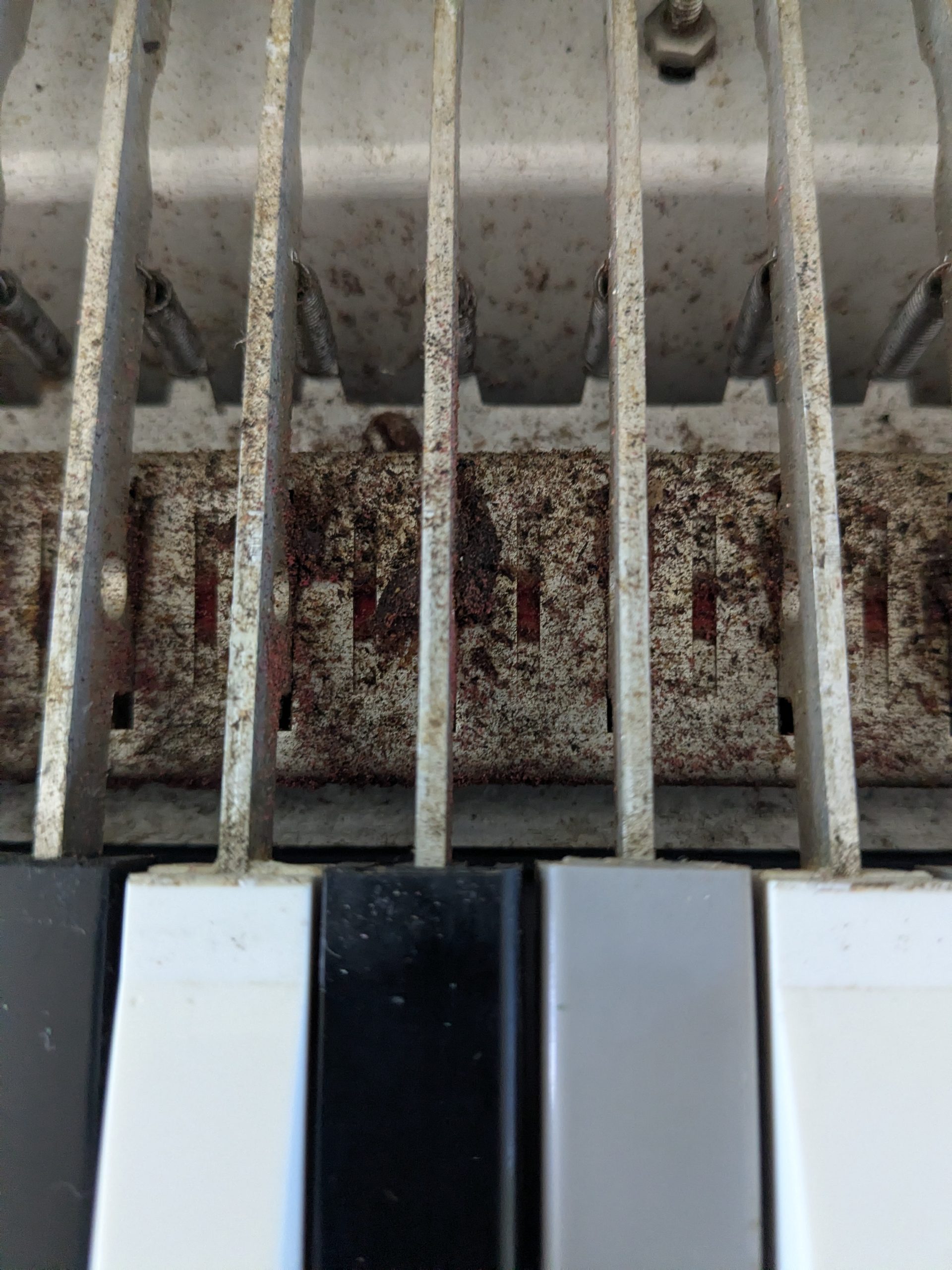
- The keybed is very dirty.
- A number of wires were wrapped up in tape.
- The reverb tank is very dirty. I removed it as a project for later.
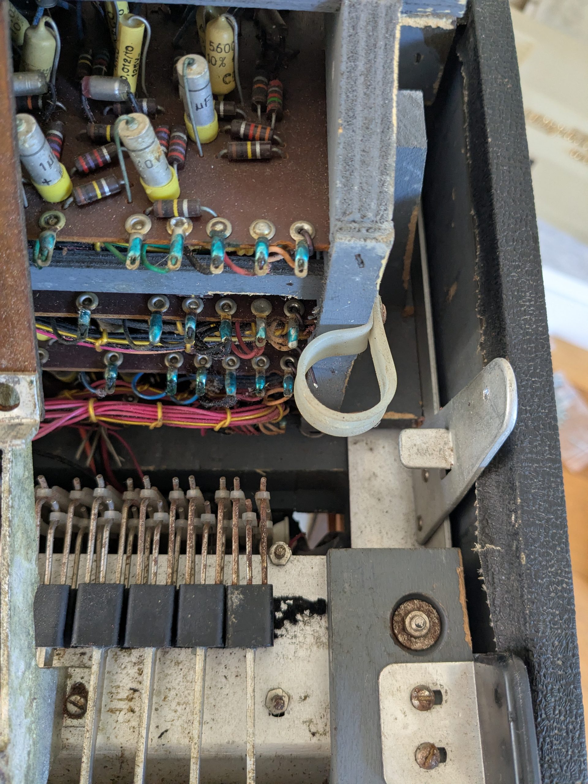
- Picked up a few more lost washers and I found a missing plastic strip that holds an oscilllator board in the case.
I decided to first give it a good clean with degreaser. It immediately made a difference.
I then bought an oscillator board, a voltage selector and a vibrato knob from a reverb seller for a reasonable price.
So…Let’s get started!
- First things first
- A full recap
- Switches
- Vibrato and percussion
- Tube noise
- Last generator board
- Bass section
- Key issues
- Reverb
- Conclusion
- Documentation
1. First things first
First I replaced the power cable. I think it had gotten stuck somewhere and was badly worn. I also replaced the plug attached to it because of the long earth pin. The schematic also pointed me to a so-called death cap. This is a capacitor on the path between the incoming mains wire and the housing (chassis) of the Farfisa, meant to prevent high-frequency noise. But what happens when, after decades, the capacitor fails? Exactly… if you’re unlucky, you suddenly have 230V on your chassis. You can replace it with a Class-Y safety capacitor, which doesn’t short-circuit but fails open internally. Another alternative is to simply remove it. You often don’t notice a difference in sound. I did the latter.
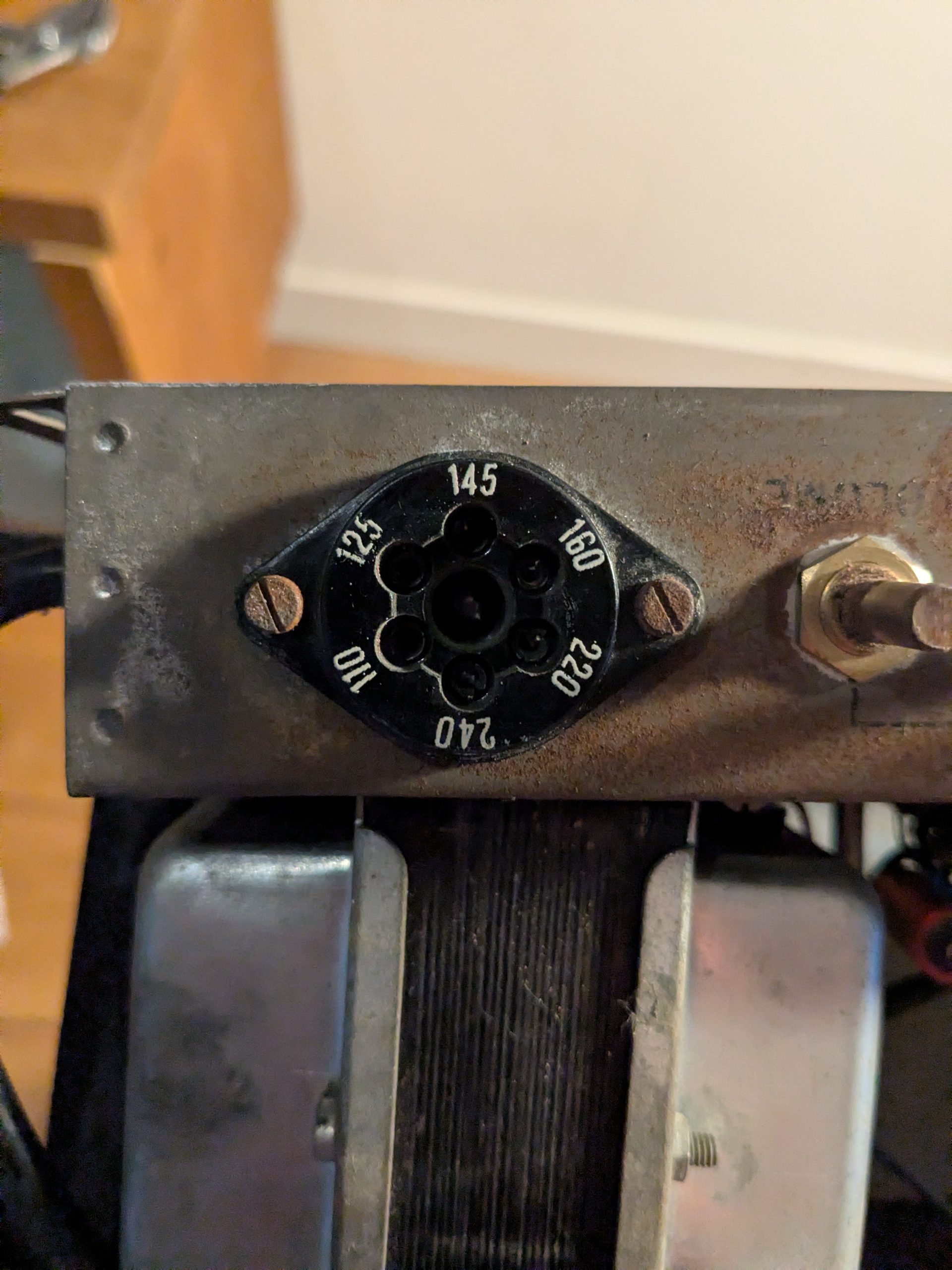
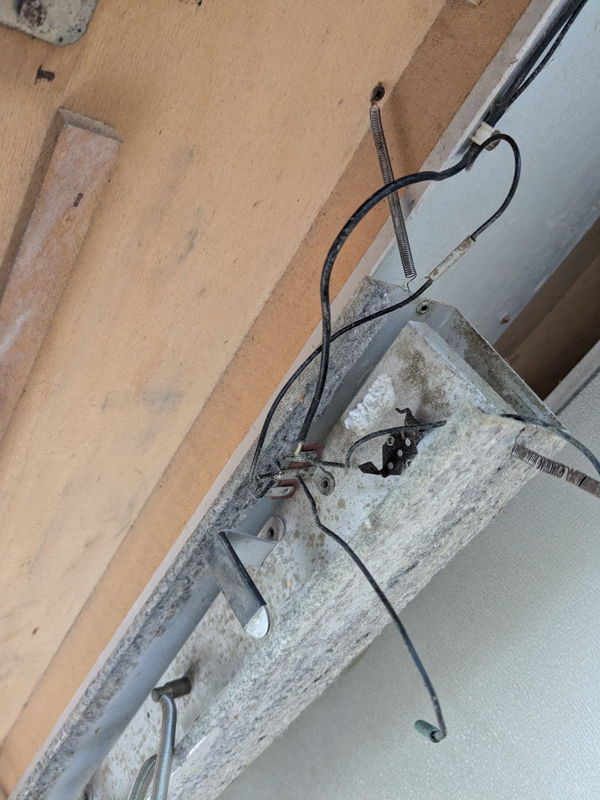
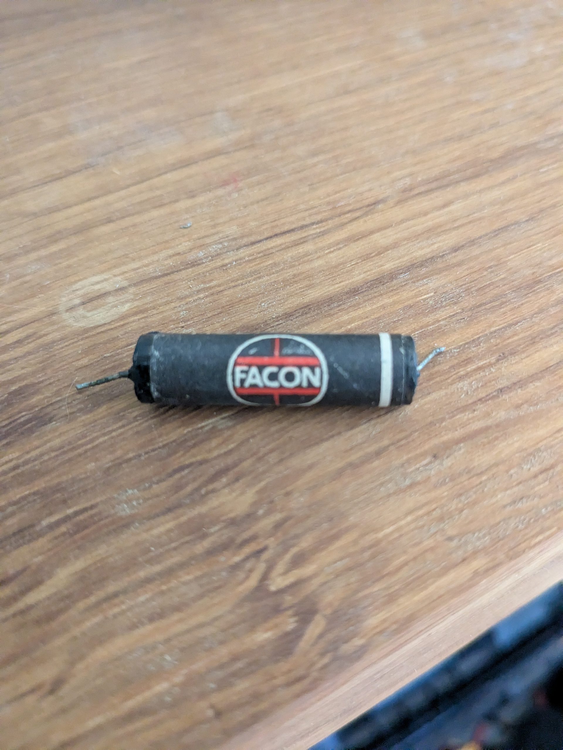
After that I started recapping the PSU. By then the voltage selector had also arrived, and I decided to hook the Farfisa up to my dim bulb tester. One press of the button and…
No smoke…!
2. A full recap
So it turns on, but something is wrong:
- The sound is very quiet. I noticed that the blue buttons at the vibrato are intermittent. When I fiddle with them, the sound comes through loud! That means cleaning and replacing the vibrato knob.
- The black bass notes don’t work.
- Some other notes don’t work.
- Quite a lot of voice tabs don’t work.
I had already decided beforehand to completely recap the Farfisa. It’s an old thing from the 60’s and I expect capacitor issues sooner or later. Replacing them was admittedly a big job (there are more than 100), but it seemed worth it. Most of the capacitors are on the generator boards, and I decided to replace those first after the PSU. That way you at least have a decent foundation if you know for sure that all generator boards work properly. You can then rule out all those boards in case of issues.
There are 12 generator boards here, and each board generates a tone that is distributed across octaves. By desoldering them all and hooking them up to your lab supply (they receive 8 volts), you can measure them well using an oscilloscope or an audio probe. I decided to use an audio probe and go through the octaves one by one on the solder lugs.
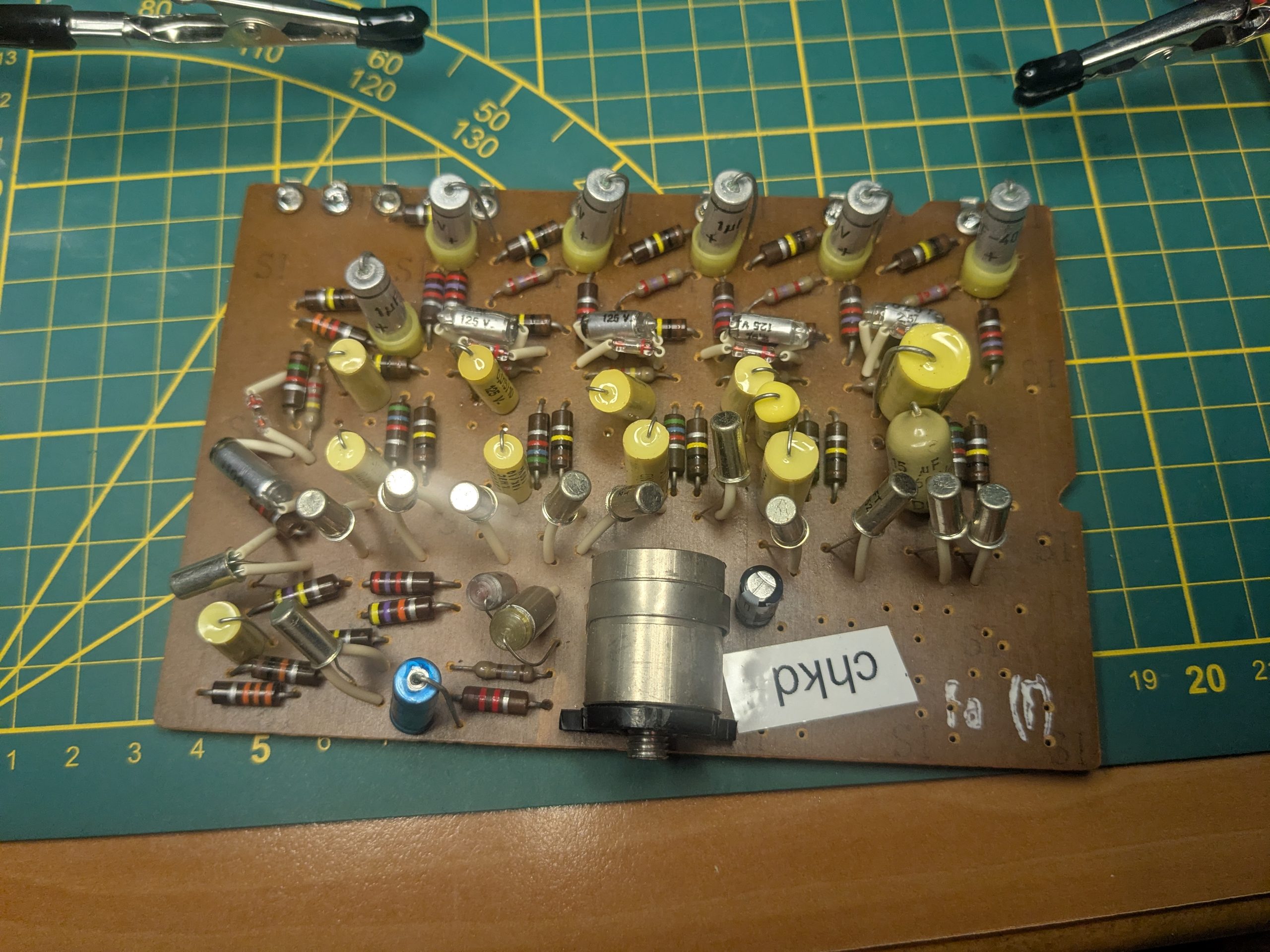
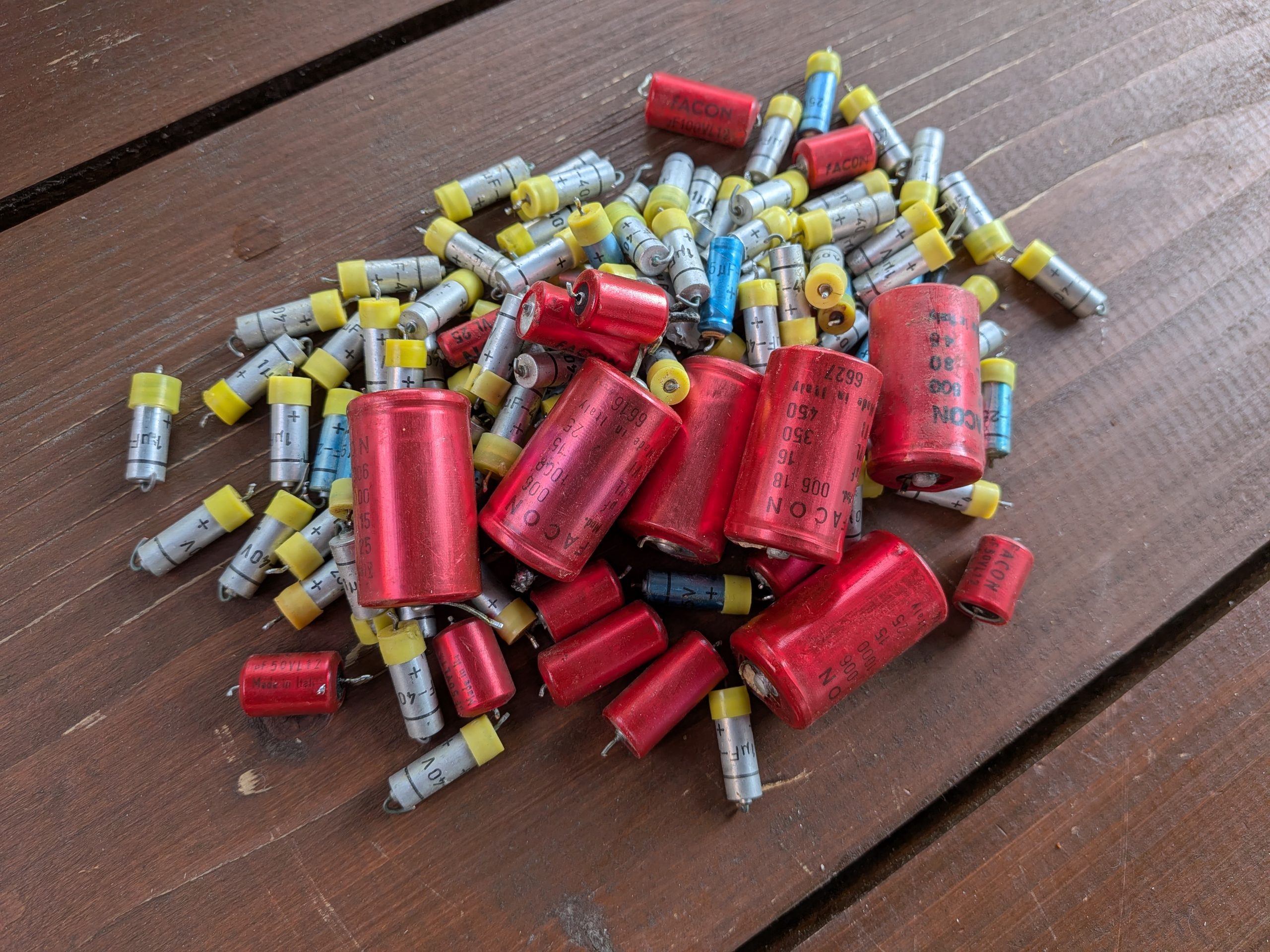
Some octaves on some boards didn’t sound right. This was often solved by a recap or, in a number of cases, by replacing a defective germanium transistor (SFT352). To replace these I took a donor generator board. That way I could better work out how many transistors I would need to buy. In the end I needed five. Since the SFT352 is fairly expensive and rare, I chose a more common alternative, the AC125. I bought about ten of them, but noticed that not every replacement was a success. Could I have received defective AC125s? Germanium transistors can often be tested well with a diode test, but things like a leakage current and hFE test aren’t done by the sellers. If they don’t measure well, issues can arise. If you want to move away from germanium, a standard 2N3906 is also a good choice. Just replace them in pairs per octave. I think I’m going to buy a good (germanium) transistor tester.
Tip: My desoldering pump kept getting clogged. I decided to remove the capacitors without the desoldering pump, simply heating the legs with a soldering iron, and this actually works much better. Just heat both points and pull the cap out, then vice versa. I did the same with transistors and I’m going to do this more often from now on.
3. Switches
So quite a lot of tabs didn’t work. A look under the switch board gave a clear reason: all the springs that were supposed to make contact were corroded. I decided to take everything apart and clean it, including the switches.
I looked into what the best way to do this was. The method that worked best for me:
- Put the switch in the pressed-in position (top side down).
- First release the lower iron clip, and only then the hook of the plastic switch. The reason is that over the years this plastic can have become weak, and you risk breaking off the tab. This probably happened to the previous owner, since there was one that had broken off (the vibrato knob). I had to buy that knob again. Getting the lower clip loose sometimes takes some force/fiddling.
- Release the springs with a hook.
- After that, the steel rod that runs through the switches can be slid out (perhaps with a little WD-40). Try pulling with a twisting motion using pliers. It helps if you remove the potentiometer (50k) for the bass volume. That way you can also clean it internally right away. Its resistance didn’t measure properly on mine either.
After that it was mainly a matter of measuring the continuity of the contacts and springs and cleaning them. I used Kontakt 60 for this.
One spring had so much corrosion that it broke off during cleaning. I solved this by soldering a small wire into the spring. That worked fine.
Some switches had crumbled a bit around the mounting point for the rod. I fixed this quickly and temporarily in a not-so-obvious way: with a kind of clay that I attached with superglue so that the rod could go through again. I wonder how long this will last, although it felt quite sturdy. We’ll find out.
I also replaced the felt under the buttons. It was completely worn out. Don’t buy felt that’s too thick, because then the springs no longer make contact. I think 2 or 3 mm was enough.
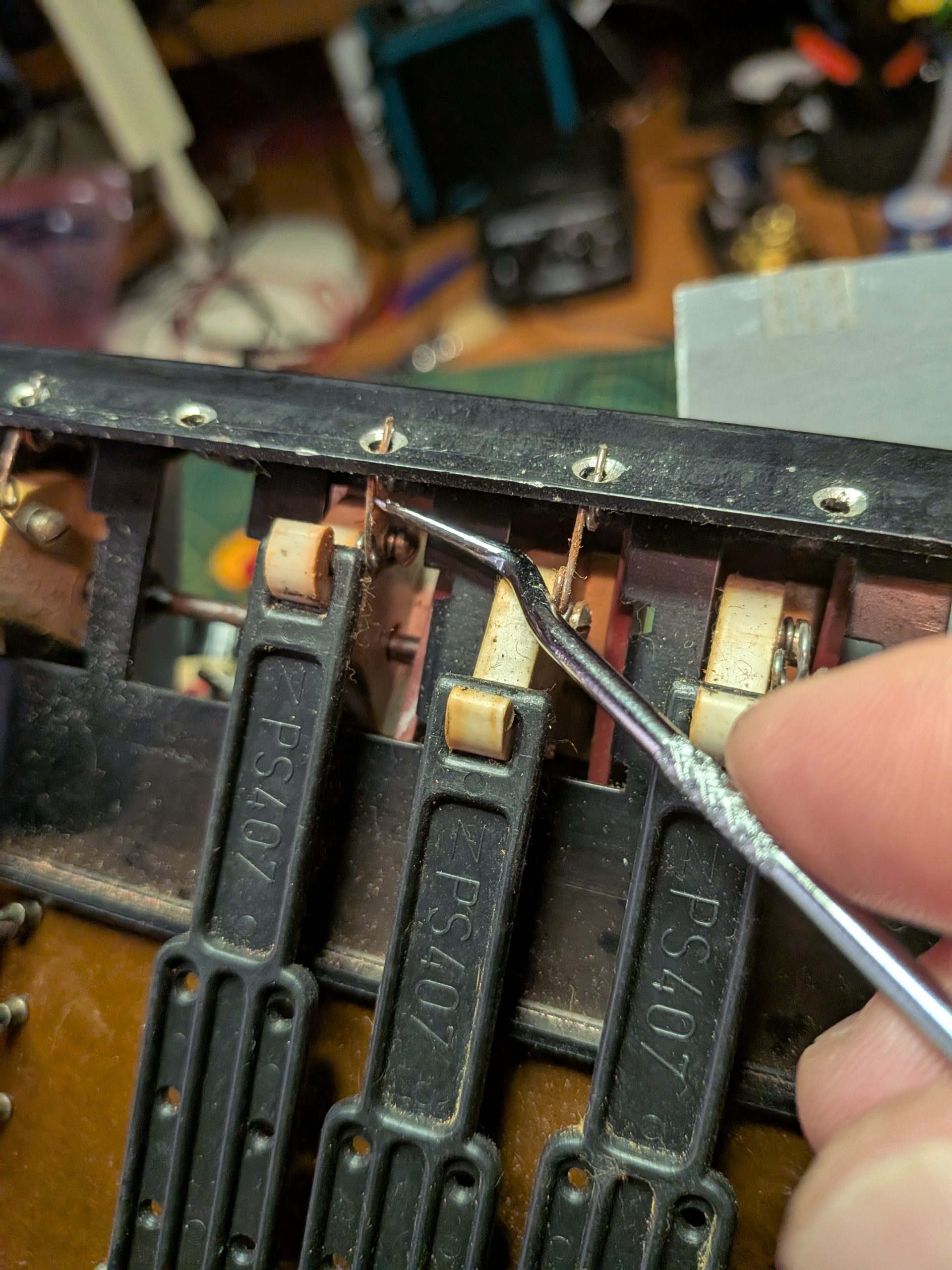
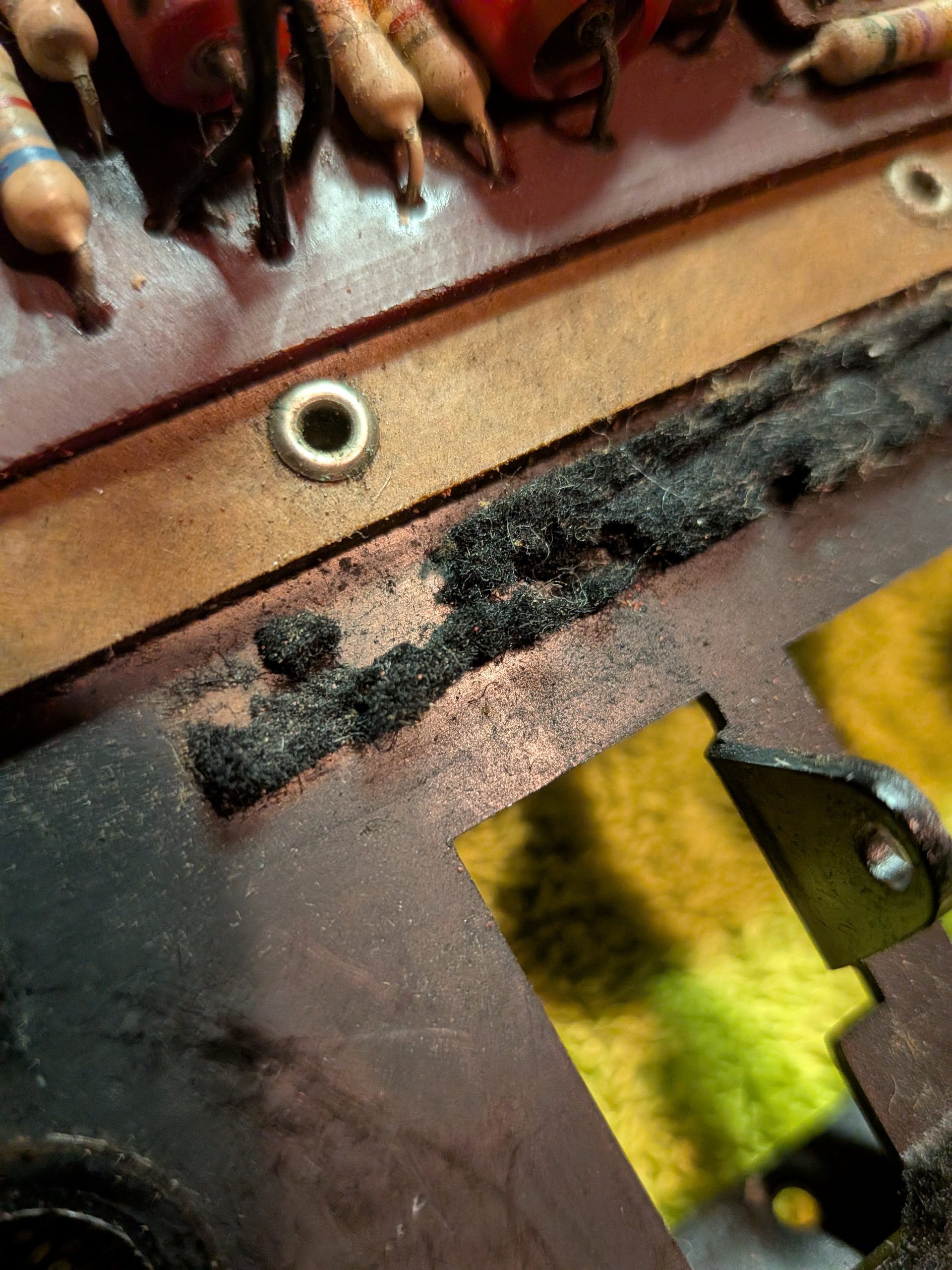
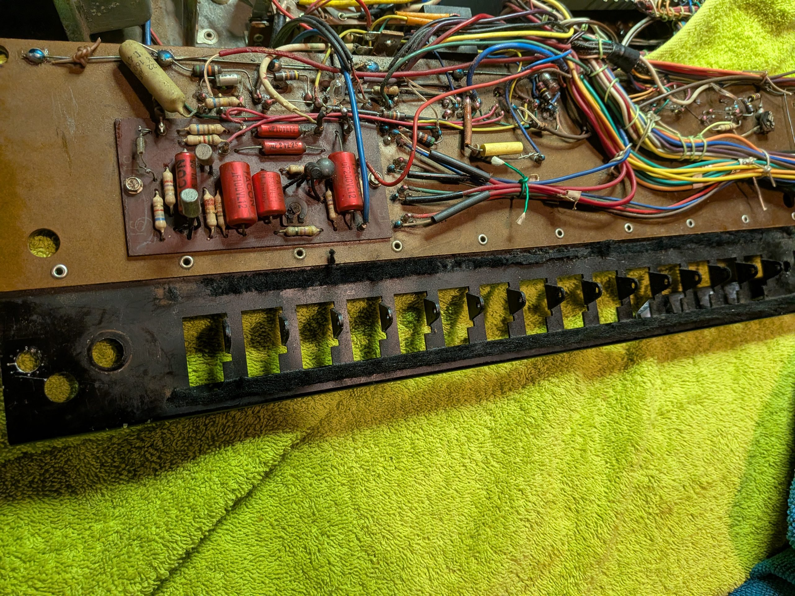
Putting the switches back
First put all the switches onto the rod.
Then hook the black plastic plate over the plastic switch.
Then put all the contact springs through.
Then attach the clip. This works best, in my opinion, by clicking in the left side first and then the right side. You can also take it out, but that doesn’t work so well. (The metal clip is a kind of clamp. Press it in briefly, turn it, and it comes out if you would want that.)
Then attach the large spring to the white plastic with a hook. Push the spring back a bit with your thumb and hold the knob in. The spring can’t shoot away through the screw, but it can shoot against your thumb. Practice this, and don’t put too much pressure on the white plastic with that hook. That hook can be brittle and break off, just like my vibrato knob.
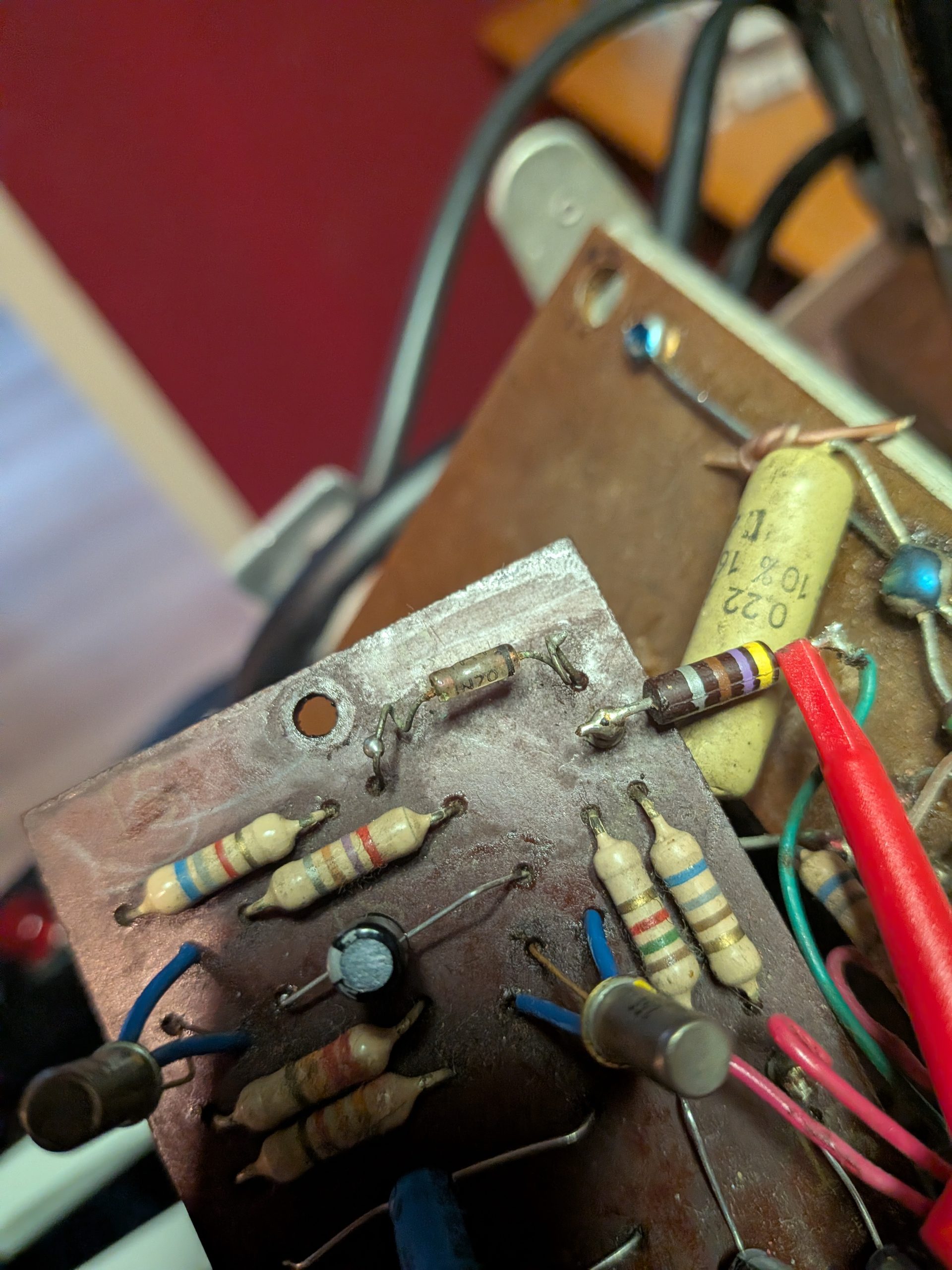
On the switch board there is also a small percussion PCB. You can unscrew it so that you can replace the components. I replaced the electrolytic caps and a few transistors.
OK, the switch board is all set up now.
What remains
- Vibrato doesn’t work yet after replacing the knob
- Bass doesn’t work yet
- Percussion button doesn’t work when I switch perc treble on
- Some noise from a loose contact on the line. Probably from the other switches?
- The oscillator still needs transistors to be bought.
- Mechanically adjust the keybed. Some registers don’t work.
- Clean the keybed. Very dirty.
- Reverb doesn’t work.
- Intermittent noise again. When poking the tubes it’s gone. Bad contact or solder joint probably.
4. Vibrato and percussion
I was looking at the vibrato PCB (which also holds the bass section) and noticed that a number of wires had come loose. When I resoldered them, the vibrato worked again. That was a simple fix.
I also saw that a blue wire had come loose near the percussion board. When I attached it, the percussion button worked too, although the long/short setting still didn’t work properly. It sounded very quiet. All the germanium transistors on the board (PA-24/1) seemed fine, but I couldn’t test leakage. I decided to replace every transistor using the donor generator board. That helped! The lamp lights and percussion long/short works again. A germanium diode was also heavily oxidized. I replaced it with an A117 diode.
After these changes it worked for a while but I noticed the long / short settings where intermittent and caused volume drops. There sometimes was a voltage drop at some point on the percussion board which lead me to the PSU. I checked all the way back and noticed the voltage after the selenium rectifier ( E250 C50) had dropped. I read these things can get a higher resistance over time which can cause voltage drops. I experimented a bit with a 1N4007 and a 2w 1.5k resistor. It measured 243V instead of the needed 275V. With 470ohm it became 255V. Still not enough. I switched the voltage selector at the back from 240 to 220V. Then it became 270V. I finally removed the resistor so I had only the diode and it became 278V which is well within spec.
After this the percussion was perfect and the little lamp was also reacting on the input of the keybed.
5. Tube noise
Uncontrolled noise often came out of the speaker, which disappeared when I tapped on the vacuum tube. I decided to thoroughly clean the sockets with contact spray and interdental brushes and resoldered the lugs. That helped. The noise was gone afterwards.
6. Last generator board
There was one last generator board which I needed to fix which I used as a donor board. . Some newly placed AC125s didn’t seem to work. For lack of replacements, I used two new 2N3906s for one pair. That worked immediately. I couldn’t really hear a difference in sound, so I’m leaving it like that.
7. Bass section
The bass section produces no sound. In the schematic, the manual bass goes to pin 9 (PD input) of the vibrato board. I listened there with the audio probe while pressing a bass key. Sound comes out. So a mechanical issue is ruled out fortunately. Next, I looked at a SFT352 transistor on the vibrato board.
Audio goes in to the base and comes out amplified at the collector. After that it goes to a trimpot, but it doesn’t seem to arrive there. The trimpot should be soldered together with the collector, but there seemed to be a gap between them. I soldered them back together. I also treated the trimpot with IPA and moved the wiper back and forth. After that the bass worked again. Unsure what caused it, but it works again!
8. Key issues
Now that I know for sure that all generator boards and switches work, I decided to look at the keys that didn’t work.
Below is the inventory:
Keys without MTB (Multi Tone Booster) engaged
4th register doesn’t work anywhere.
Keys with multibooster (MTB) engaged
Bass
– B1, B2 don’t work. Applied DeoxIT. Didn’t work. After 20 minutes they suddenly did work.
16′ register
– B2, B3, B5 don’t work. They suddenly work again too. A loose contact somewhere?
G#5 doesn’t work.
8′ register
– B2 didnt work but now it works again.
G#4 doesn’t work.
4′ register
– G#3 doesn’t work.
– The last octave doesn’t work via MTB. But all 4 registers of the non-MTB tabs don’t work either.
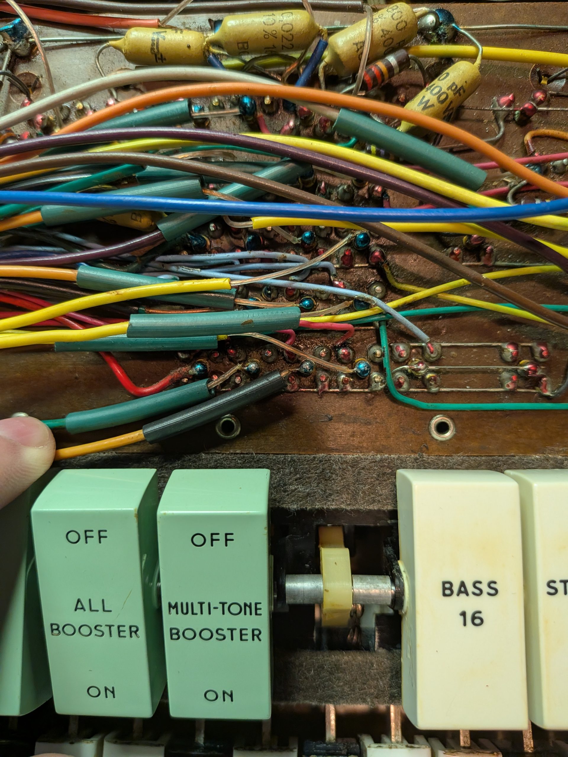
After looking around the MTB switch for a while, I noticed that the third octave of the 4th register had now stopped working too. Apparently I had fiddled a wire loose near the MTB switch. When I resoldered it, it worked again.
Via MTB I did have sound from the 4th register on other octaves. According to schematic SE-10, the issue could lie with the busbars, since they come out directly at the MTB switch. I followed the yellow wire and arrived at a spot on the underside of the Farfisa where something had been done before. Tested the wire again and sound came out. It was hard to reach, so I’m glad it was only the wire that wasn’t making good contact. Resoldered it, and now everything works again on the 4th register.
2 2/3′ register
– C#3 doesn’t work. A wire was loose on the bottom of the organ.
The G# issue
- Checked G# generator board tones. Tones are there…
- No signal comes through the FD10 board either.
So the problem lies somewhere in between. - Switches, MTB or non-MTB, same issue. So it’s not that either.
- Checked connection of the bars: fine.
- Is it the matrix board? Checked there and measured continuity with point 2d of the generator board.
There was no continuity here! Desoldered wire 2d. Then there was continuity. Resoldered 2d. Now there is continuity.
G# tones work again!
After a while C3 under register 4 didn’t work anymore.
On the matrix board, 2 grey wires had come loose that went from C3 of 4′ to 8′. They were ridiculously thin wires with no continuity. I soldered another wire between those points as a replacement.
After that C3 worked again.
Tip: All wires are pretty thin. If you happen to have individual tones missing its worth checking the other side of the organ. A good chance a wire has come loose then. I did have a few more that had gone and had to resolder them again.
9. Reverb
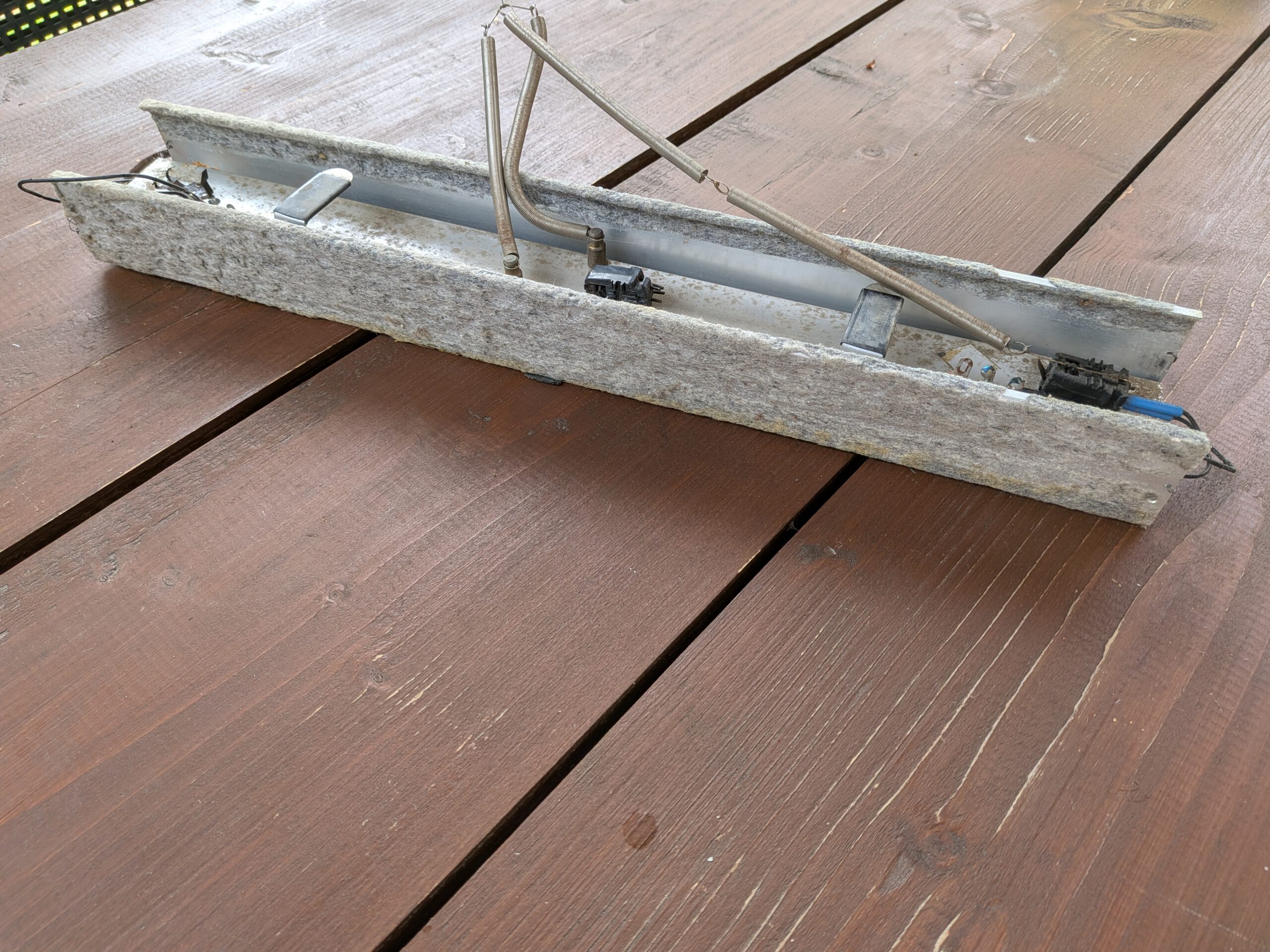
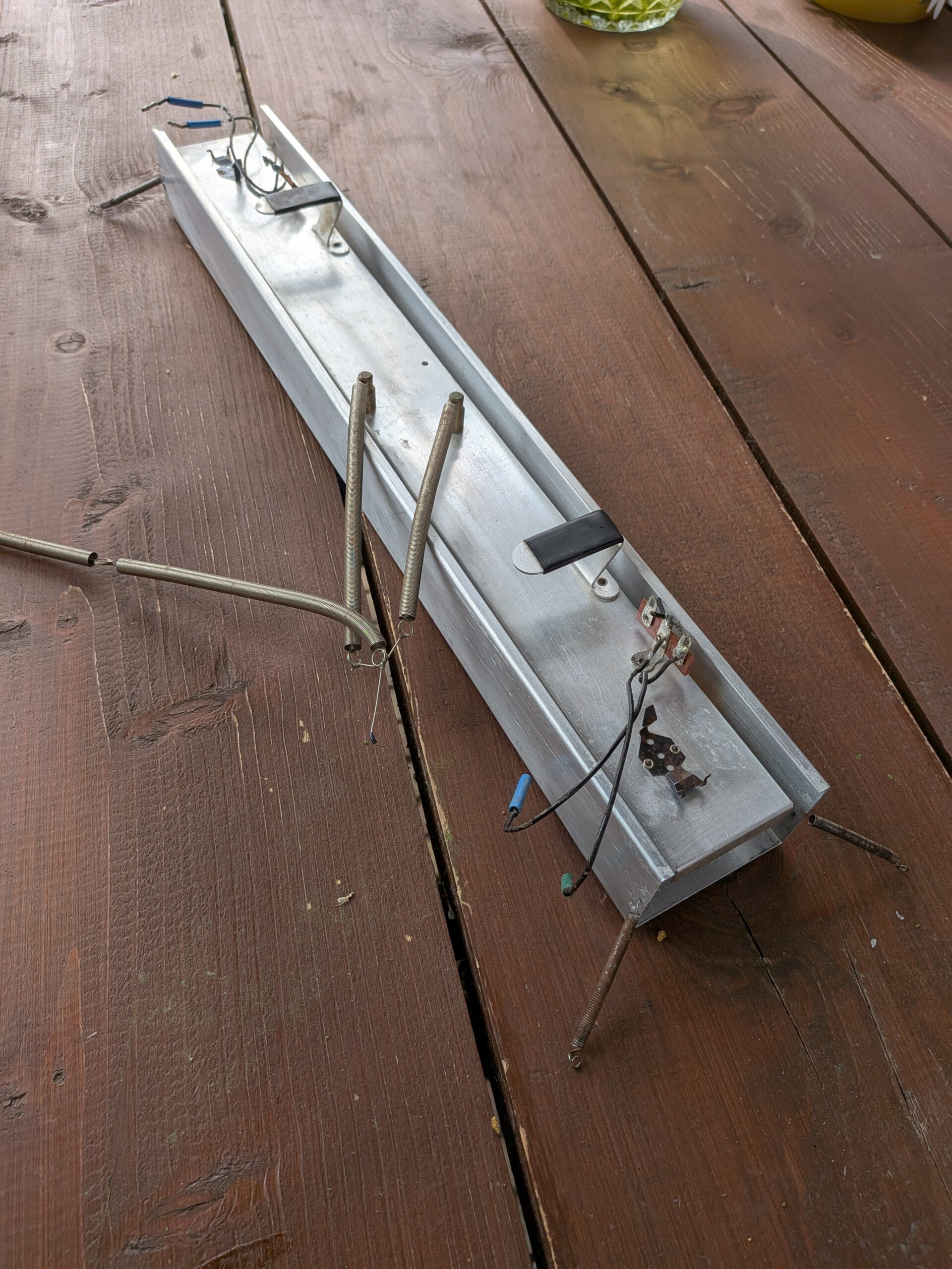
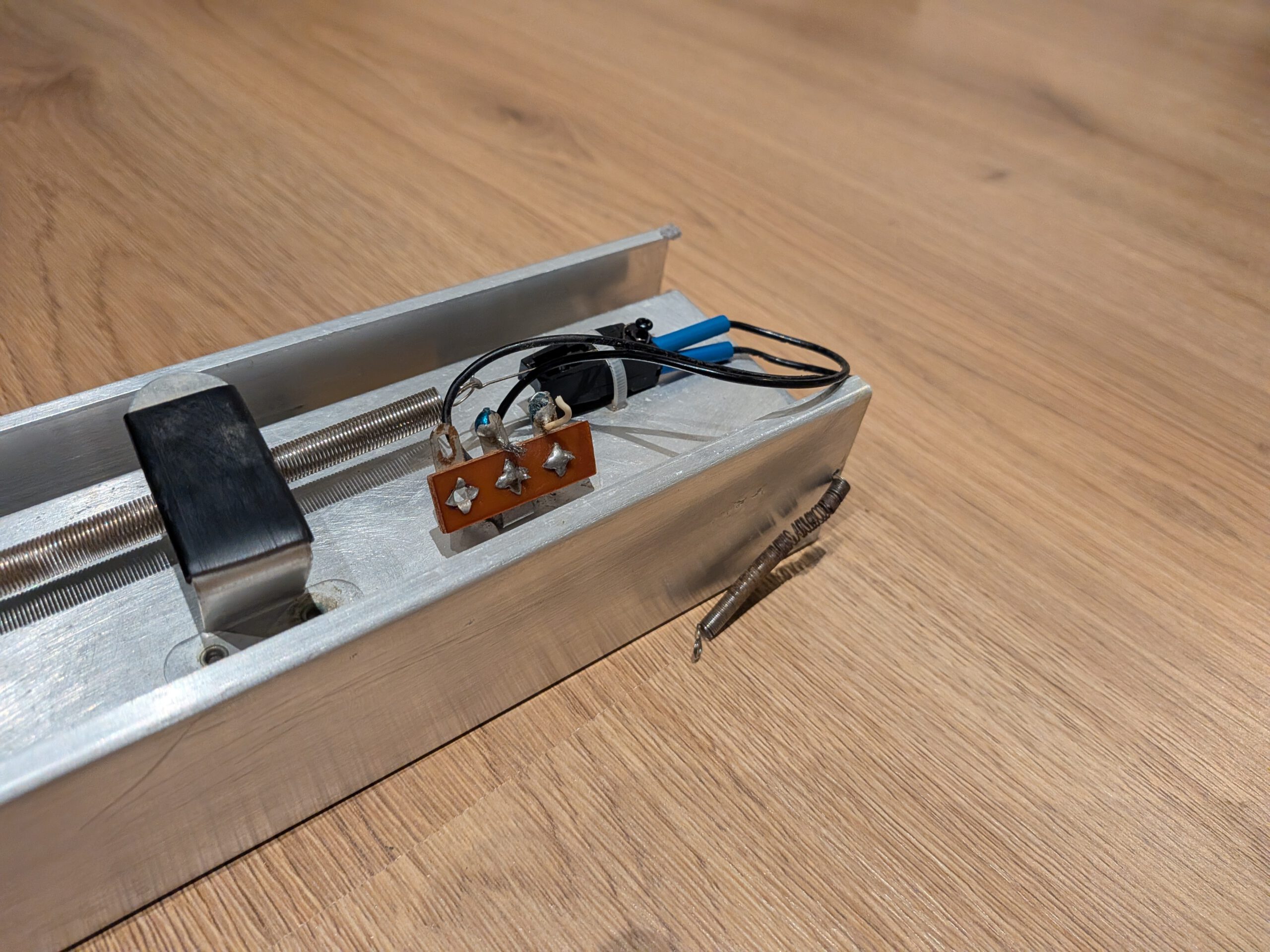
The Farfisa Compact Deluxe has a spring reverb mounted on the underside.
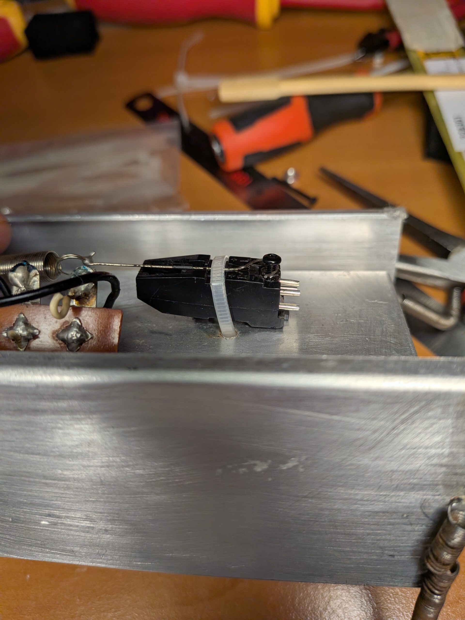
The covering on the outside of the tank was badly crumbled on mine. It released lots of small particles. I removed it and cleaned it thoroughly. One cartridge that came with it was broken and the other no longer tested well.
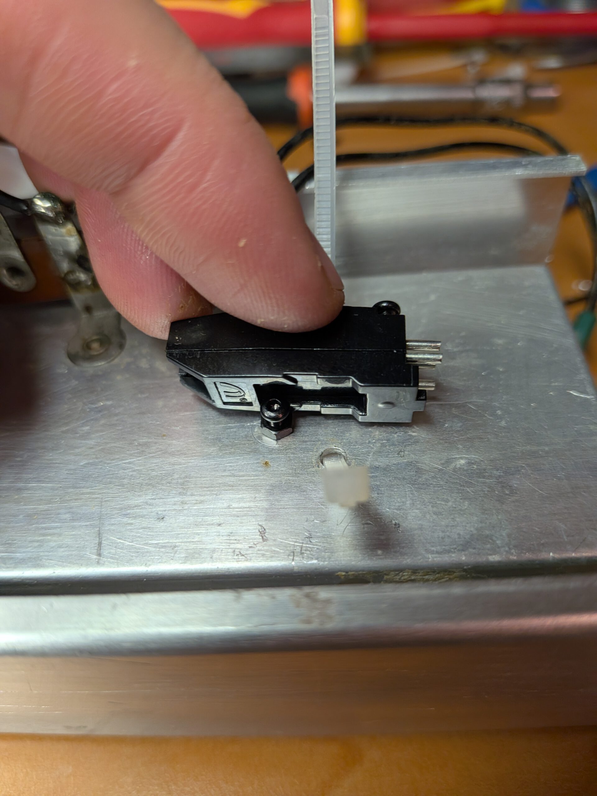
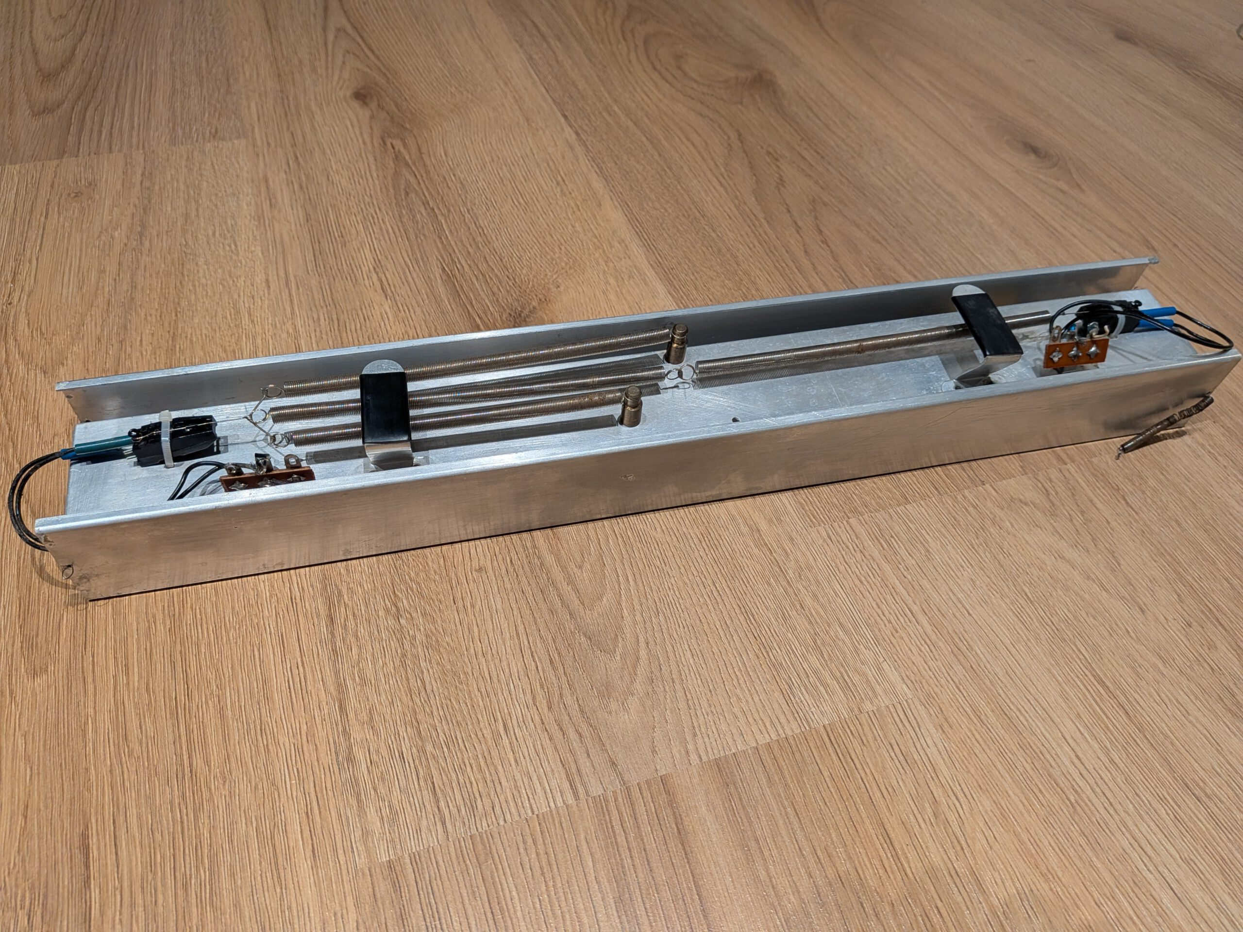
I bought two new ceramic cartridges from Temu. I mounted it on the spring reverb as followed:
- I removed the original cartridge and mount
- I drilled a third hole for an adjustment screw for the height.
- I used the original two holes for a tie wrap and adjusted the screw underneat for the right height so that the spring sits on the yoke of the cartridge.
- I removed a screw from the top of the cartridge and replaced it with a larger crew so it can hold the hook of the spring.
I tested it, but unfortunately it didn’t work. No sound was going to the recovery amp even when I hit the springs. I want to take another look at it separately in the near future, so I have disassembled it again for now. This way, I can take my time at the workbench to figure out what is going wrong. If I get it fixed I”ll post a follow-up here.
10. Conclusion
This project was similar to the Octave Cat. Both were in very poor condition and required a complete makeover. I’m glad I did it, because the sound is beautiful and unfortunately, this is another one I’ll have to keep. The repair process actually went quite smoothly. When I first opened up the Farfisa, I was a bit concerned about the mess of wires running all over the place. Fortunately, everything was in order on that part of my unit, but I can imagine that if a wire comes loose, you’ll spend quite some time tracing where it needs to be reattached. Other than that, everything is easy to repair as long as you have the schematics.
11. Documentation