
1. Buying and history
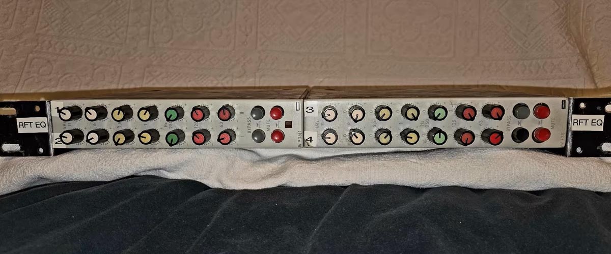
A few weeks ago, I was looking for new restoration projects when I came across a pair of equalizers on German eBay. They were an RFZ W735 and an RFZ W735/1, both of which, according to the seller, were no longer working.
RFZ (Rundfunk- und Fernsehtechnisches Zentralamt) was the central institute responsible for the development of radio and television technology in the former German Democratic Republic (East Germany). It was a government organization operating under the Deutsche Post.
Founded in 1962, RFZ was established to provide the state broadcasting service with high-quality professional audio equipment. Because imports from the West, such as equipment from Telefunken or Neumann, were severely restricted, RFZ developed its own now-legendary mixing consoles, microphone preamplifiers, such as the V781 and VK290, and equalizers, including the W735/1.
The RFZ W735 is a discrete stereo equalizer featuring seven carefully selected center frequencies: 63 Hz, 125 Hz, 250 Hz, 1 kHz, 2.5 kHz, 6 kHz, and 11 kHz. Each frequency band offers a maximum boost or cut of ±11.5 dB, with a 3 dB bandwidth of approximately three-quarters of an octave, corresponding to a Q factor of about 2.
2. The RFZ W735
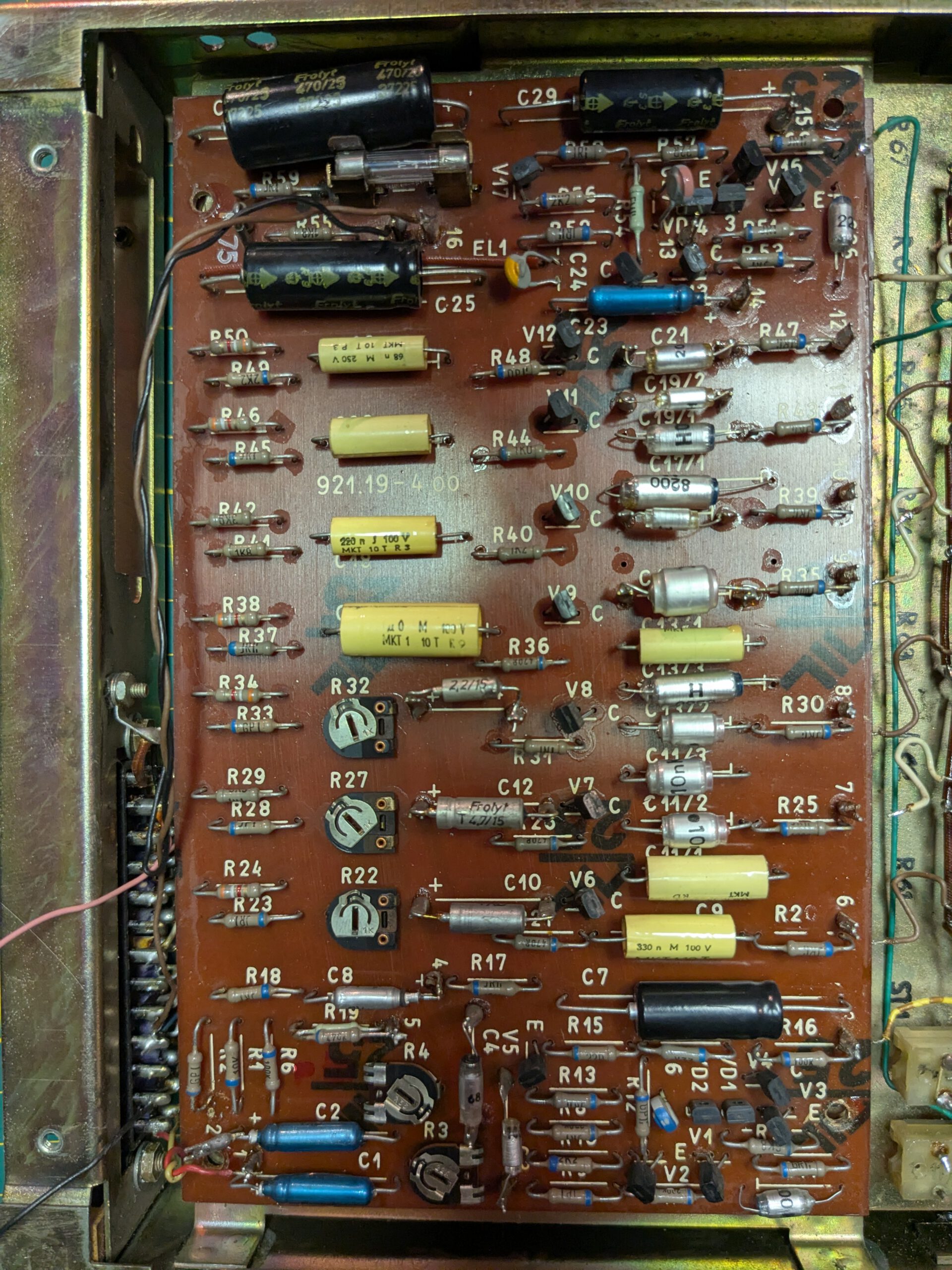
First, let’s take a look at the W735. The unit is easy to open by removing two screws on each side, allowing the side panels to slide off. Each channel has its own PCB. I started with channel 1 to check whether the power supply rails were still present. The 24 V rail was fine, but the 10 V rail was missing.
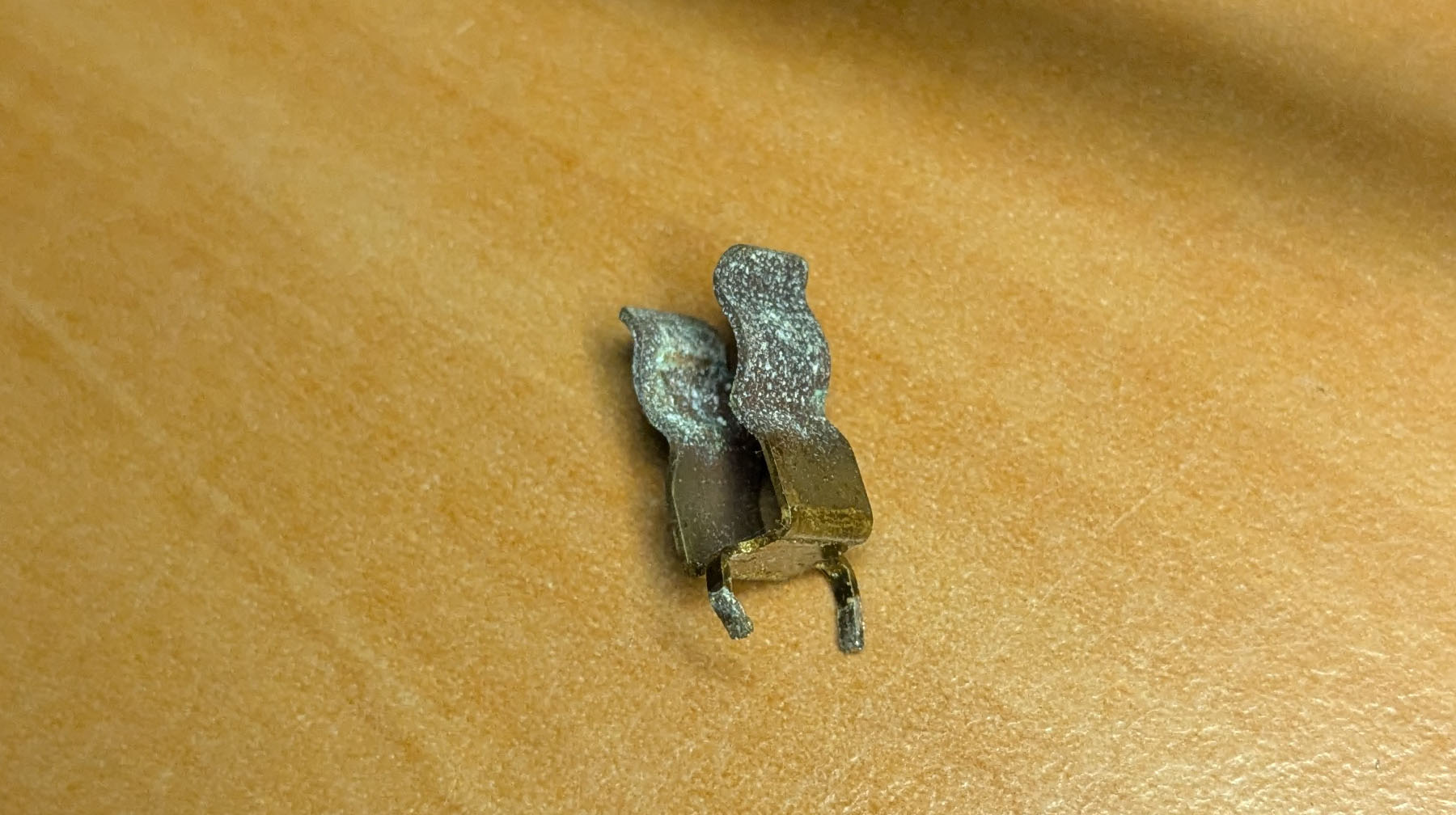
I noticed some corrosion on the fuse holder, so I decided to clean it first. I desoldered both fuse clips, lightly sanded them, and cleaned them with IPA. After reinstalling them, the equalizer came back to life. My impression was that the fault was intermittent, and cleaning the fuse holder appears to have resolved the issue.
To test the equalizer, I bought a simple function generator (FG200), which I connected to the input. The oscilloscope was connected to the output. I wasn’t familiar with the best way to verify the EQ’s gain range in dB, so I asked Claude for advice. It suggested using the following formula:
dB = 20 × log(Vpp measured / Vpp reference)
The test procedure was as follows:
- Set all EQ controls to their center positions.
- Set the function generator to a 1 kHz sine wave.
- Adjust the output level of the function generator until the oscilloscope reads 2 Vpp. This is your reference value.
- For each frequency band, generate the corresponding test tone. For example, to test the 63 Hz band, generate a 63 Hz sine wave.
- Record the Vpp at maximum boost and maximum cut, then provide those values to Claude. It calculates the gain in dB using the formula above and immediately checks whether the results fall within specification. I had already provided the service manual as input, so it knew the expected values. This turned out to be a very quick and efficient way to verify the equalizer.
On channel 1, the 6 kHz band was not behaving quite as it should. The measured values jumped around when applying boost. I sprayed a little DeoxIT into the potentiometer and worked it back and forth several times. That solved the problem. Channel 1 was now fully functional.
Next up was channel 2.
Channel 2 suffered from exactly the same issue as channel 1. The fuse holder was corroded, causing problems on the power supply rails. I decided to replace both fuse holders on both channels, as this appears to be a common weak point.
Unfortunately, after replacing the fuse holder, channel 2 stopped working altogether. After some troubleshooting, I found that several transistors in the input amplifier stage had failed. The collector-to-emitter junctions were shorted. After replacing the faulty transistors, the equalizer came back to life. I had never encountered a collector-to-emitter failure before, and it’s not something I normally check when testing transistors. I usually only measure the base-to-collector and base-to-emitter junctions. This was another good reminder not to overlook the collector-to-emitter measurement when troubleshooting transistors.
All frequency bands on channel 2 measured within specification.
3. The RFZ W735/1
On this equalizer, I immediately replaced the fuse holders as well, since they were also corroded. I also replaced the fuse itself, as it didn’t look to be in particularly good condition.
I also performed the frequency response test on this unit. On channel 1, the 125 Hz band was noisy, and on channel 2, the 250 Hz band showed the same behavior. I treated both potentiometers with DeoxIT, after which they worked perfectly again.
4. Fixing another W735/1
I tested both equalizers on some acoustic drum tracks, and I was pleasantly surprised by how good they sound, especially when driven a little into saturation. The selected frequency bands are more than adequate for my needs when processing drums. I also tried them on the master bus, where they performed exceptionally well.
By chance, I came across another W735/1 on a different auction site at a very attractive price, so I decided to buy that one as well. These equalizers appear to be quite rare, so I couldn’t pass up the opportunity. According to the seller, it was still working a few years ago, but they were unable to test it because the connector was missing.
On German eBay, I found a suitable 26-pin connector for the equalizer, along with the matching connector housing. (Search term: 26 polige Messer.- und Federleisten Steckverbinder mit Gehäuse SIEMENS Stecker.)
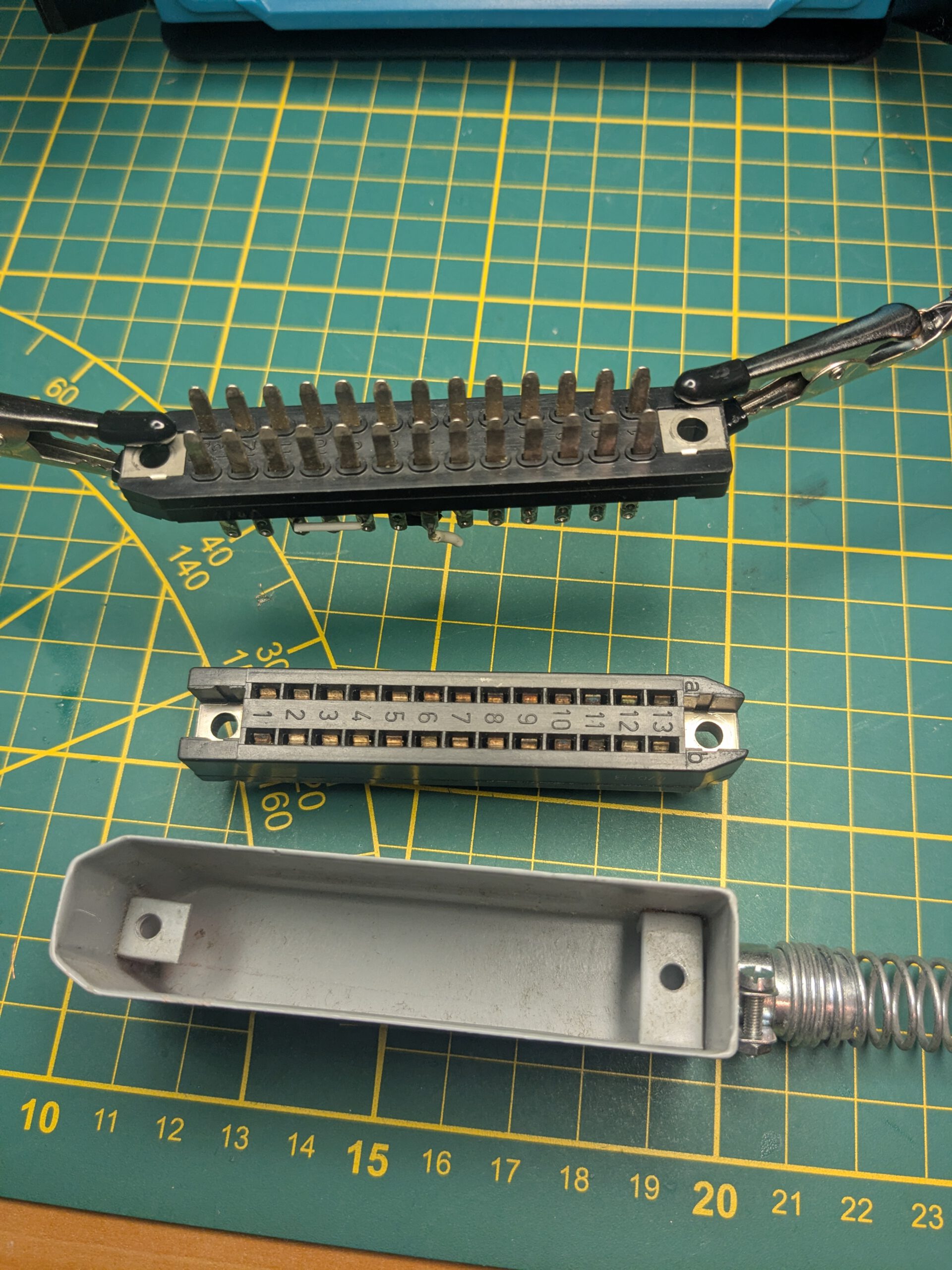
I connected the W735/1 to my bench power supply and, to my surprise, it worked immediately. The next challenge was figuring out the correct pinout for the connector and wiring everything up properly. That turned out to be quite a job.
5. Case closed
At first, I considered building a 19-inch rack to house the two equalizers. Now that I have three of them, that idea no longer made sense. Instead, I decided to build a custom enclosure using an oak plank I had lying around. I cut the wood to size and glued the pieces together using dowels.
I also had to modify the power supply so it could power all three equalizers. I made some changes to the internal connector to create enough room for the additional wiring. One important detail was the negative supply voltage required by the equalizers. The positive terminal is tied to ground, while the negative terminal operates at -24 V.
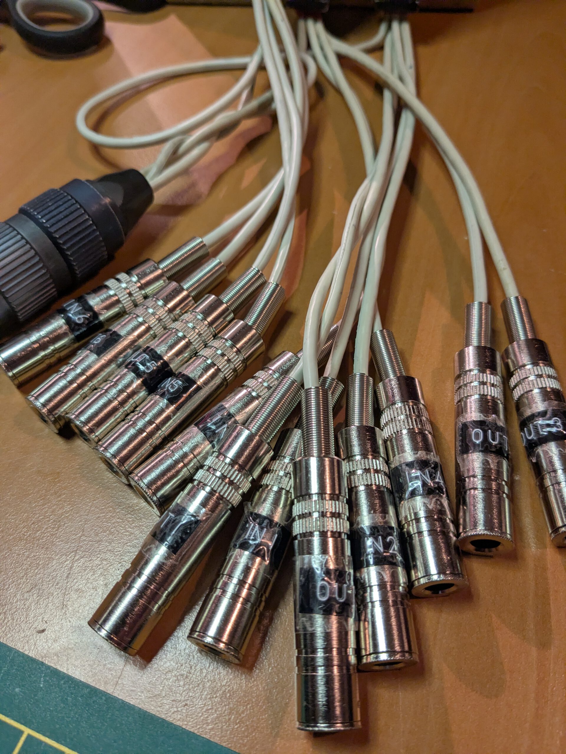
The W735 and W735/1 originally came with cables terminated in male jack plugs for the inputs and outputs. I didn’t find that very practical, as the cables were too short to be useful with something like a patchbay. Instead, I soldered female jack sockets to all six inputs and outputs.
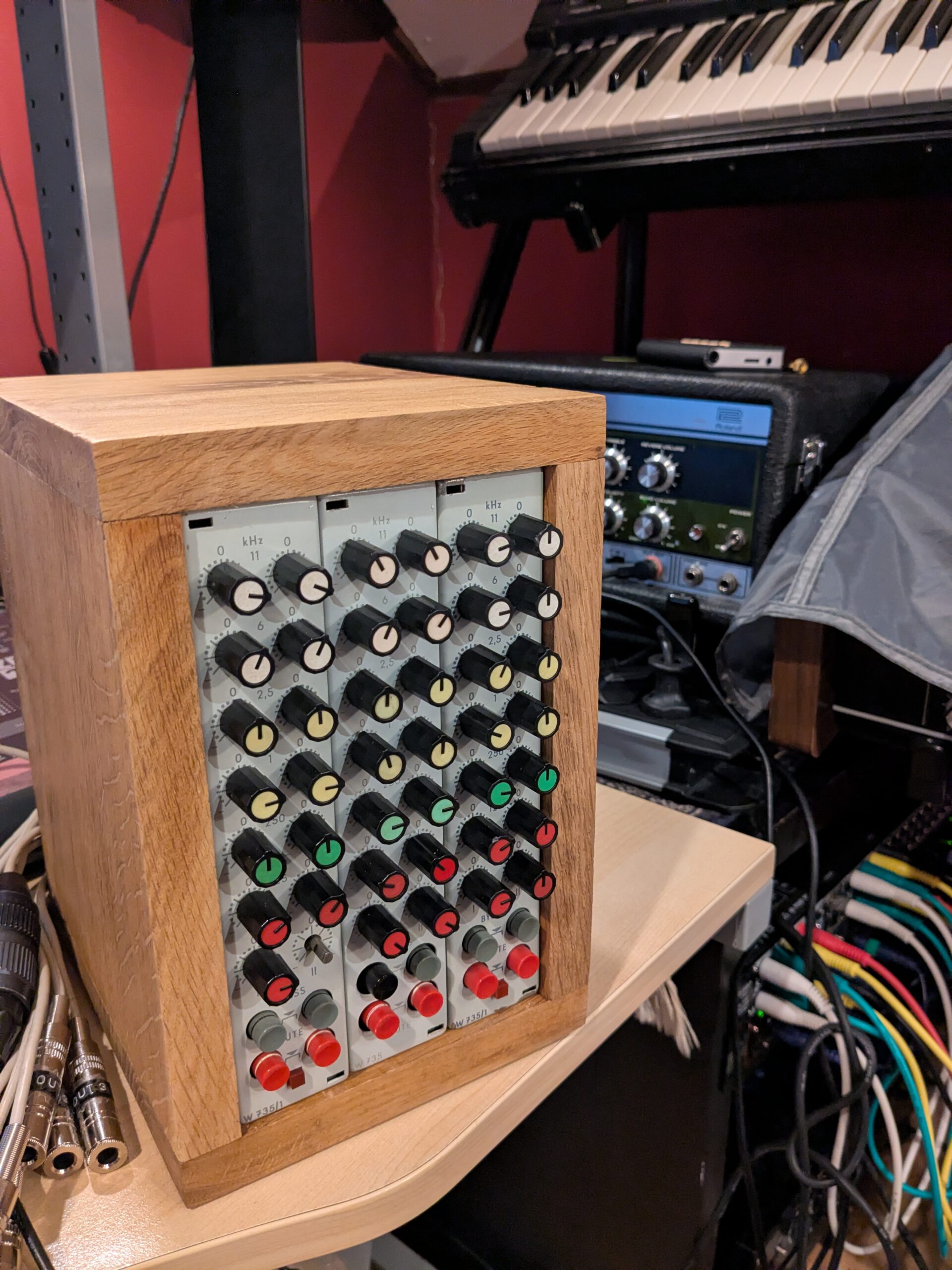
Below is the final result! I am still missing one red knob. It was not included with one of the equalizers, so I will have to find a replacement somewhere. [Edit: Found the knob already from a friendly vendor from Berlin!]
All in all, another successful project.