
- About my last project
- My new project
- Motor revision
- Mechanical adjustment
- Replacing the capacitors
- Modification
- Conclusion
- Documents
1. About my last project
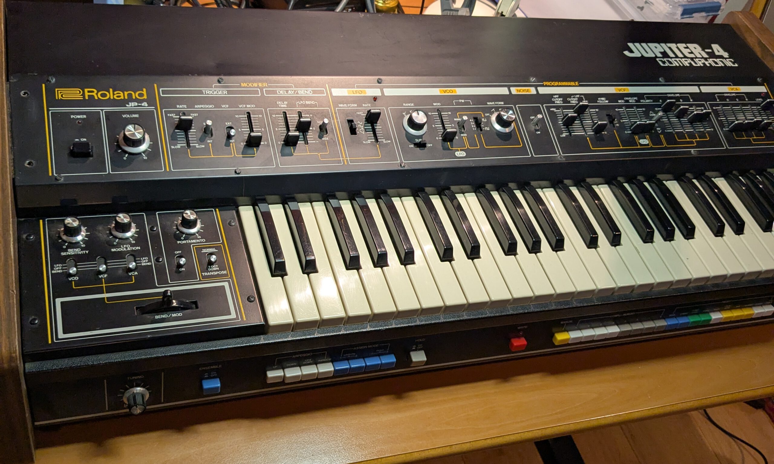
About six months ago I saw a nice opportunity to buy a Roland Jupiter 4 synthesizer from Germany. It was sold as defective but looked very nice, and the price was good enough for me to give it a try. A couple of friendly Germans even offered to deliver it.
Once it arrived at home, some things worked but quite a lot did not. I saw that there had been battery leakage and multiple functions no longer worked. Presets and save did not work, the keybed did not trigger properly and notes repeated after 16 notes. The LFO did not work properly, the noise did not work, the high pass did not work. In short, quite a lot of issues. And I also still wanted to replace all capacitors. Anyway, I started with good motivation, but I could not properly solve the issue with the repeating notes. I was heading in the right direction on the key assigner board, but it took too long because I kept ending up on the wrong track. I wanted to make music with this synth and there was still a lot of work left. Eventually I decided to send it to a synth repair technician (Artefacts). In the end he fully restored it and now it plays perfectly again. Apparently there was an error in the schematic and a modification had been made in my Jupiter 4. That did not really help with tracking down the fault.
I think doing some smaller projects makes more sense, since I also have another hobby (making music).
2. My new project
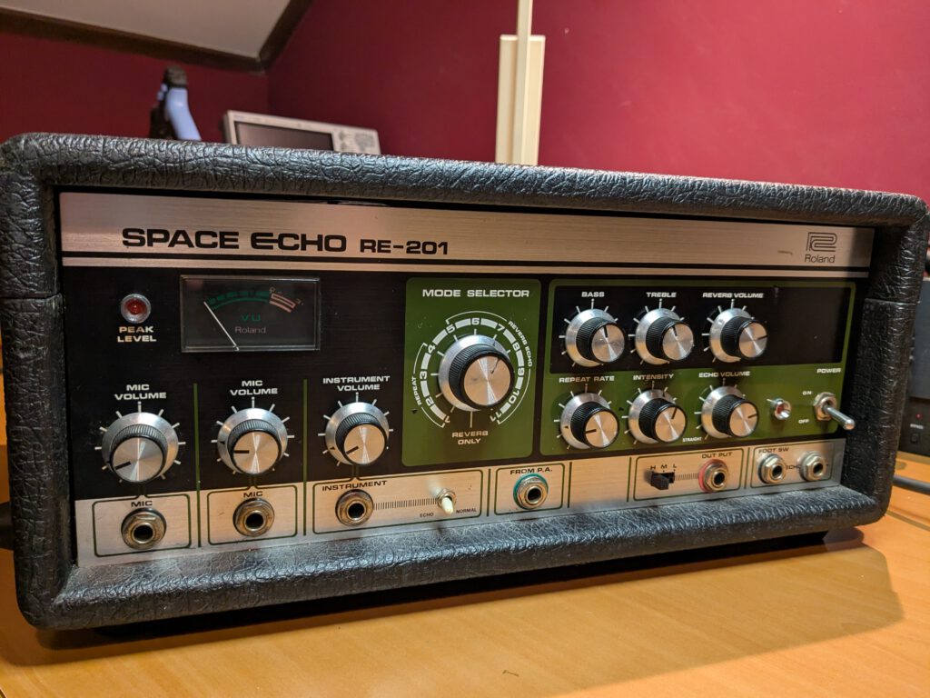
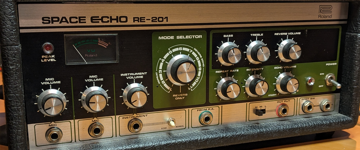
So a smaller project (I hope). The Roland RE-201 Space echo!
The Roland RE-201 Space Echo (from the mid-1970s) is an analog tape delay with a built-in spring reverb. The echo is not generated digitally; instead, the audio is recorded onto a tape loop that passes several heads: one record head, multiple playback heads, and an erase head. Because the tape is moving, the signal reaches each playback head slightly later. That’s your delay.
The motor speed determines how long that delay is, and this can be adjusted on the front panel (Rate). In addition, there are different modes that select different playback heads, giving you different rhythmic patterns. With the Intensity knob, part of the output is fed back into the input, allowing you to increase the number of repeats all the way to self-oscillation.
There is also a spring reverb that can be combined with the echo.
I bought the Space Echo about ten years ago. It immediately became one of my favorite studio devices. I use it for guitar and synths, but drums also go through it. I really love the sound and the imperfections it creates. The only thing that always bothered me was that the motor made a lot of noise due to worn bearings. I waited quite a long time to repair it, but now that I have completed a few projects I think this is doable.
What I want to do is definitely overhaul the motor. Echofix in Australia offers an Ultimate service kit to refurbish your RE 201. This also includes two new bearings, since these motors are no longer available. Echofix does make new motors themselves, but those cost around 430 euros. In addition, I want to refurbish the echo itself, so replace all capacitors and adjust everything properly. A few years ago I also discovered that my RE 201 has a modification. Next to the footswitch there is an extra jack. I tried to see what it does, but so far I have not been able to figure it out without opening the RE 201. So in chronological order:
- Motor overhaul and adjustment
- New capacitors
- Check the modification
3. Motor revision
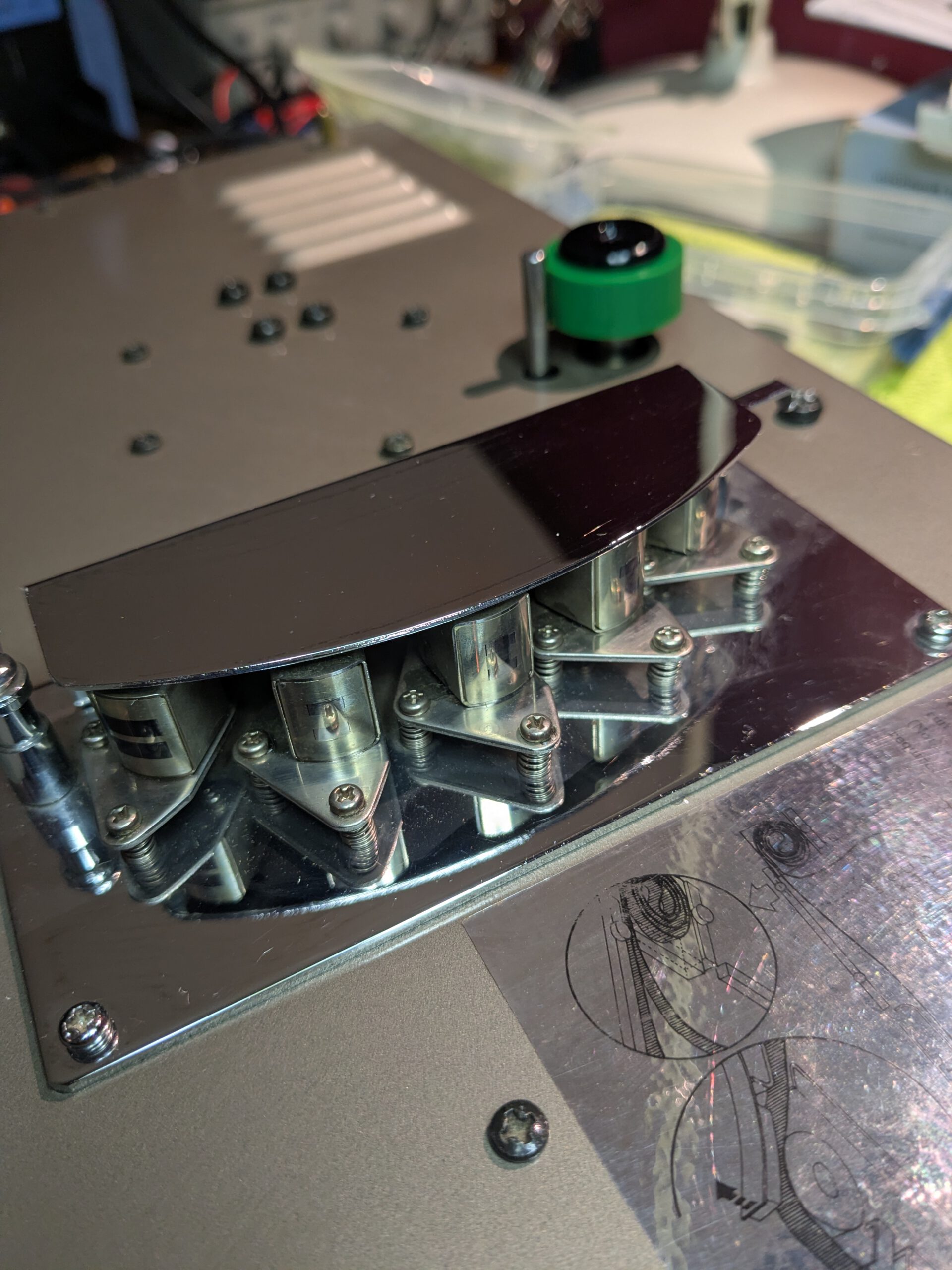
To open the RE 201 you need to remove five screws on the bottom and two on the side. On the two side screws there are two brackets that you need to remove.
Next, to loosen the motor you must remove the top section where the tape sits. After removing the tape you need to remove four screws. Two screws with a plastic spacer at the tape entry. Two at the heads, one with a spring and one without a spacer. The screws have an unusual size. With a large screwdriver I had much more grip than with a smaller one. After that you can remove the motor, which is fixed with four screws.
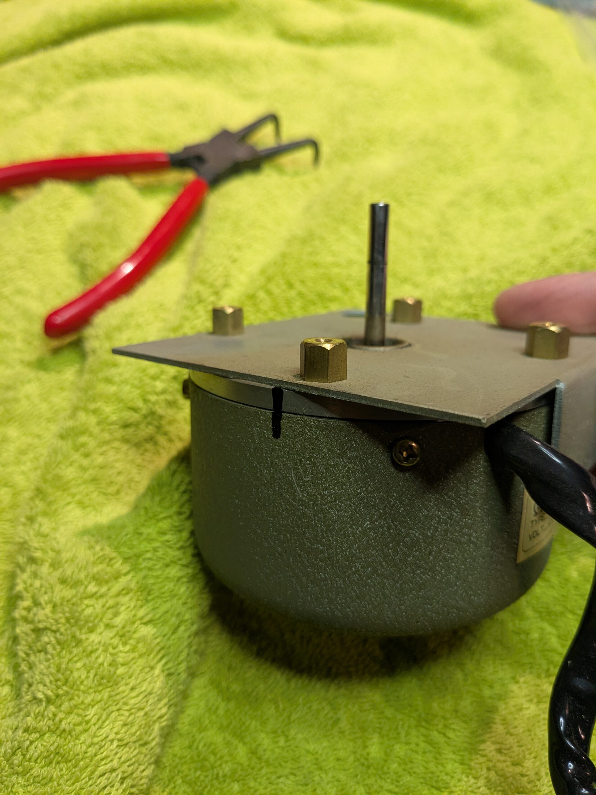
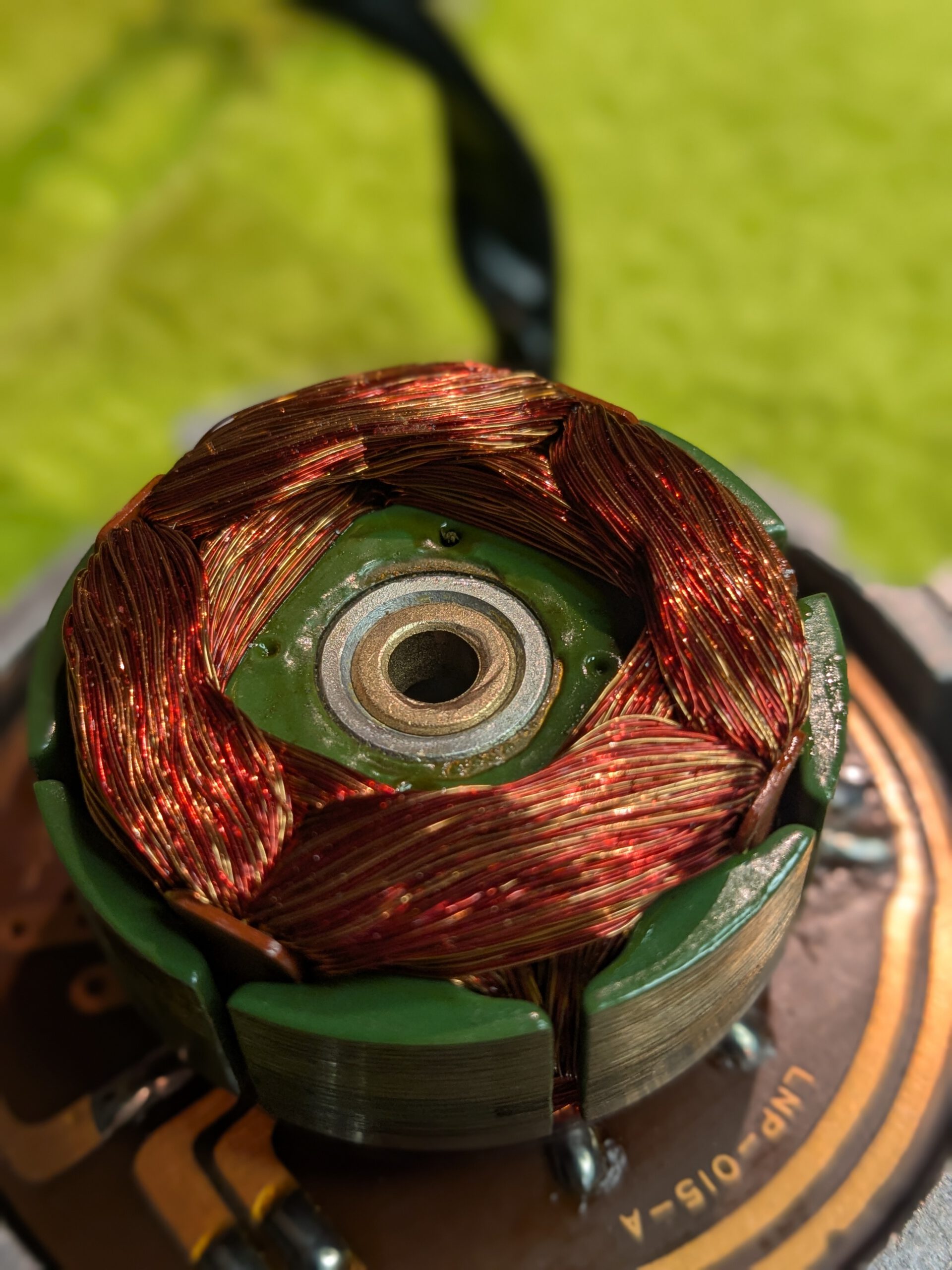
When you open the motor you need to remove some washers (keep them in order). There is also a circlip. For that you need internal circlip pliers.
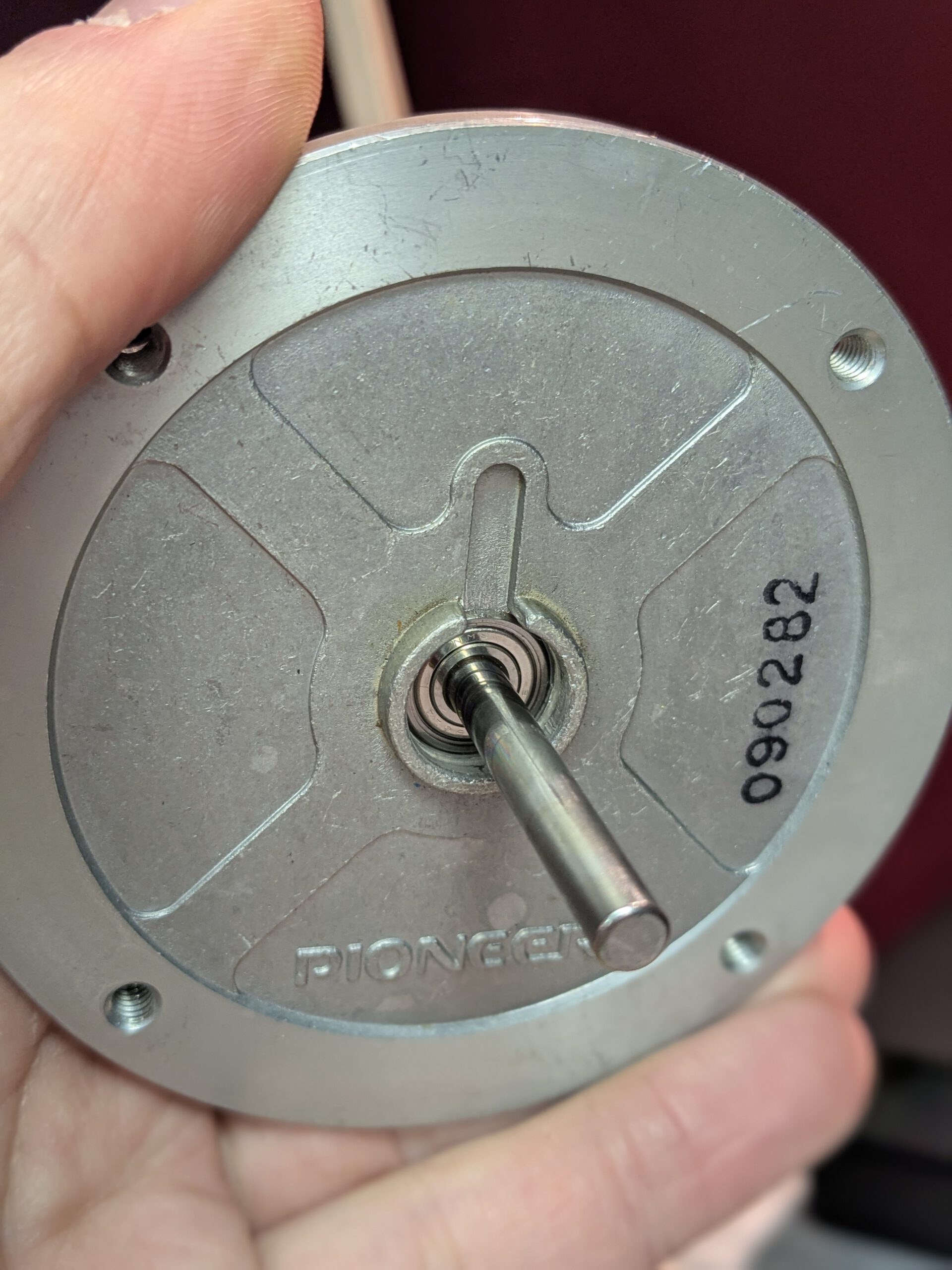
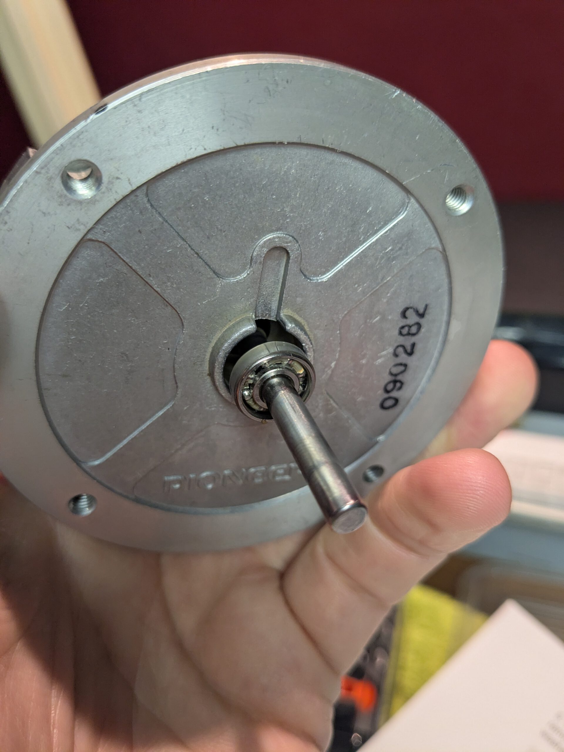
I then had a lot of trouble getting the bearing out. There is no space around it to pry it loose and you can only access it from one side. Eventually I managed to remove it because with some pressure the housing came loose from the bearing. That gave me much more grip to pull it out. Of course this is not a solution if you want to keep the bearing, but I knew for sure this one was already worn. I hesitated about replacing the second bearing as well. You can only reach it after replacing the first one, and since I was not very skilled at this yet, I decided to replace the second one too. Even though this one might still have been good (Echofix says it almost never needs replacing). If that one turned out to be bad later, I would have had to remove the first bearing again, which I really wanted to avoid. In the end I carefully reassembled everything. This revision job was a bit more difficult because of the stubborn bearing, but overall the instructions from Echofix were written very clearly.
4. Mechanical adjustment
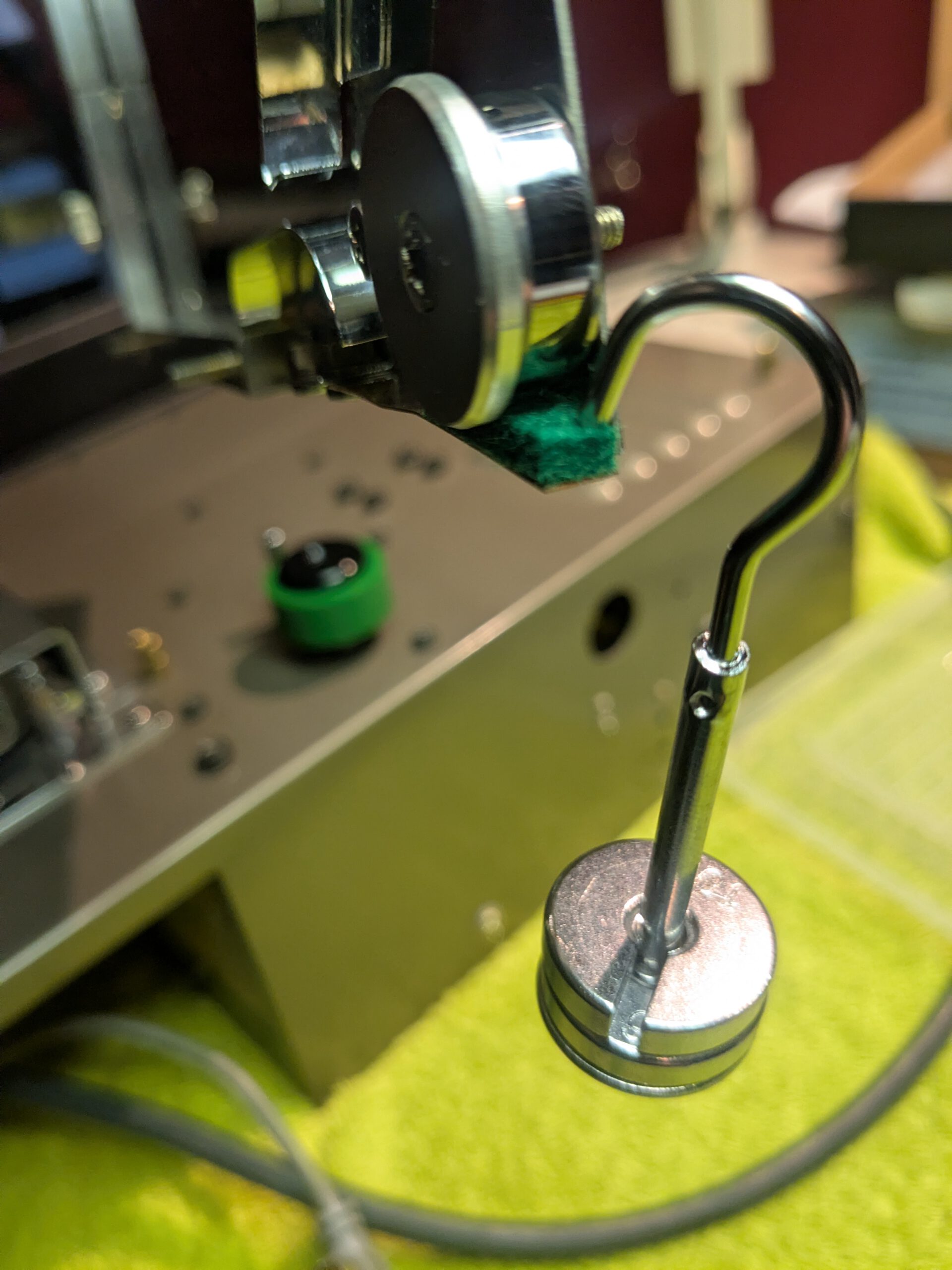
With everything open I could easily access all mechanical parts. The service kit also contained parts I wanted to replace, such as the tape tension spring and a tape feed bearing with improved pinch roller. All of these were easy to replace. What I also wanted to do was adjust everything according to the service manual. Some parts like the pinch roller and the tension spring require a specific pressure. The Roland service manual clearly explains how to do this using weights or a spring scale. It also gives tips on how to set everything so that the distances are correct. This is important for the tape mechanism, since even small deviations can affect tape alignment on the heads. This is also described well in the Roland service manual. I also cleaned the heads with IPA and installed the new tape.

After putting everything back together, it was time to power it on and see if everything worked properly. Fortunately it did, and the motor was very quiet. Not comparable at all to how it was before with the damaged bearings.
5. Replacing the capacitors
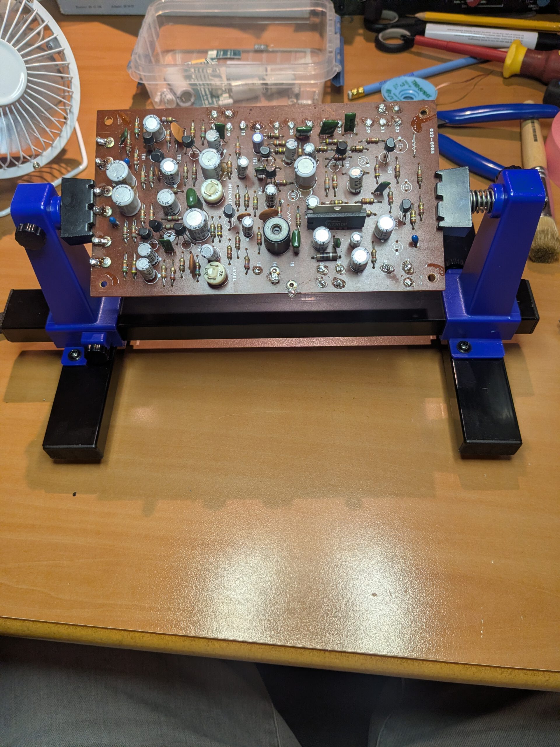
Ok, time to replace the capacitors. There are two larger PCB boards: the PSU and the Echo board. I decided to start with the PSU board.
I have never encountered a board with so many soldered wires. The PSU board has 24 soldered wires that need to be removed, and the echo board has around 30. On top of that, the wires are cut very tightly to length. This was going to be a challenge.
While desoldering, I noticed near the end that a few eyelet solder lugs were broken. These appear to be quite fragile. I had not applied much force. The wires were wrapped around them, which made removal harder. On the echo board I would need to be more careful.
Once removed, I desoldered all capacitors and installed the correct values. About three capacitors were glued in place. I used a normal hair dryer to soften the glue. Then I could easily scrape it away with a piece of credit card. Honestly, I did not expect this to work so well.
I considered testing the board before soldering all wires back, but I saw that I needed three voltages for that. My lab supply could only provide two variable outputs, so that was not an option. I decided to take the risk and solder everything back directly.
I cleaned up all wires and stripped them where needed. Some wires were not neatly bundled, so I soldered them together and used heat shrink. There was also one solder lug that needed three wires, so good preparation was important. Eventually everything went back in place and I tested the unit. It worked fine.
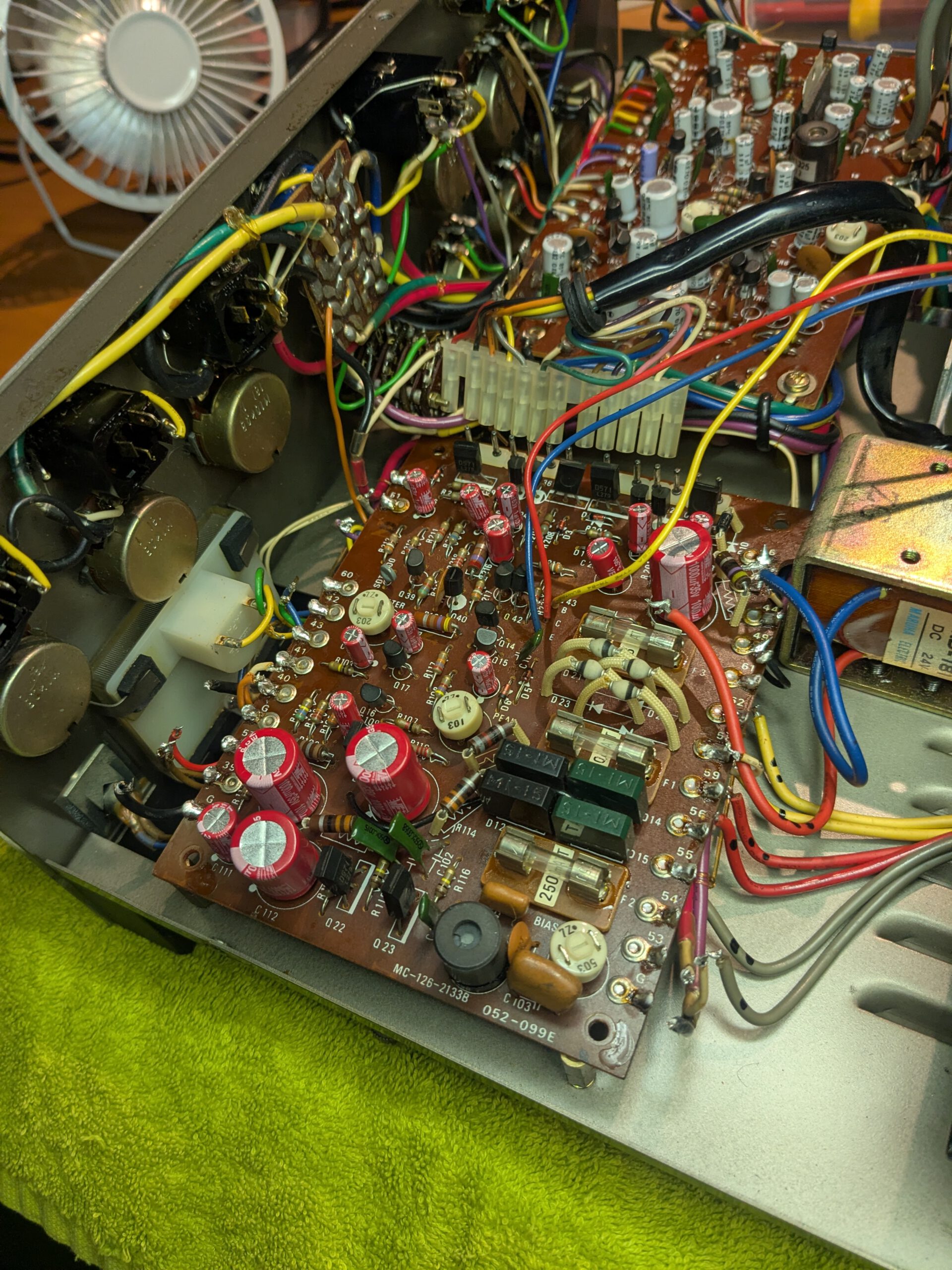
After that I did the echo board. With more care I desoldered the wires from the solder lugs. That went better. When I flipped the board over, I noticed a lot of dried flux. It really did not look nice. Also, on this board all capacitor leads were soldered flat against the PCB, with no space between the capacitors and the board. So I could not cut them off. Everything had to be removed carefully from the solder side.
I tried several methods with mixed results:
- Trying to get under the lead or try to move the lead with the soldering iron and apply slight pressure. This did not always work if it was too tight, and you risk slipping due to the pressure.
- Using the desoldering gun to pull the pin into the nozzle, remove the solder, and bend the pin at the same time. Again: This did not always work if it was too tight, and you risk slipping due to the pressure.
- First removing the solder with the desoldering gun, then heating the lead with the soldering iron and gently bending it with a small screwdriver. This worked best most of the time.
Because of this it took longer than I hoped. After soldering everything, I cleaned the board with IPA. That worked partially. It became somewhat cleaner, but the old flux did not come off. It mostly smeared and made the PCB sticky. I decided to remove the flux residue with acetone and then clean again with IPA. That worked much better and the PCB looks a lot nicer now.
After some fiddling I soldered all wires back and tested the RE 201 again. Fortunately everything worked fine!
6. Modification
I did not investigate the modification on my RE 201 very thoroughly, but from what I saw someone wanted to duplicate the footswitch. The wires from the original footswitch were soldered through to the new socket. In my opinion this mod does not work properly (the echo does not switch off like with the original switch), but I did not really feel like digging into it. Maybe later I will do the sound on sound mod and use the socket to install a switch.
7. Conclusion
All in all, this was a job that was quite doable. I was not looking forward to removing and reinstalling the PCBs, and I am glad both worked on the first try after recapping. Otherwise I would have had to figure out how to power them separately to troubleshoot.
The service kit also included transistors, but I decided not to replace those. If they ever fail, at least I have spares.
In the end, the hardest part was getting the bearing out of the motor, and carefully desoldering the capacitors was time consuming, but not particularly difficult.
8. Documents